• The move to the new server is done. There are some software and database maintenance updates in process. This has us passing the hat around to help out. We appreciate any donations. Seriously, even a dollar helps. The payment page may be found here - https://www.audiokarma.org/support.html

Luxman receiver R-1040 idle adjust

Duffalora

Active Member
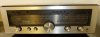
I've just finished recapping this Luxman (image 3) and I also changed out the 10k DC offset pots and the 330 ohm idle adjust pots on the power amp board.

Offset at the speaker terminals is now set at less than 1mv on each channel.

What I'm having trouble with is the idle adjust. I follow the service manual instructions (image 1) -- connect the multimeter across the fuse grips, set it to MV DC and turn the receiver on. The reading rises from 00.00mv to 00.06mv (image 3). This reading is the same on both channels and it doesn't change at all when I turn the pots.

The pots I've installed are correct -- 330 ohms (they are stamped "331"). I measured the ones coming off the board and measured the ones I put in to make sure. I also continuity checked my installation.

Also, I've been running the receiver all weekend with these pots set at their midpoint and it sounds great. The heatsink barely gets warm.

Any ideas as to what I might be doing wrong here?
 

Attachments

  • luxman idle adjust.jpg
    luxman idle adjust.jpg
    59.6 KB · Views: 43
  • luxman multimeter.jpg
    luxman multimeter.jpg
    66.7 KB · Views: 46
  • luxman.jpg
    luxman.jpg
    34.6 KB · Views: 38
Register to hide this ad
Are both channels doing that?
From the second picture it looks like the fuse is removed, if I see it correctly.
Do measure the resistance between the base and emitter of that Q204a and for Q204b transistors. It should change between 560 and 910 Ohms as you are adjusting the trimmer pot. From your readings it looks like there is a break in that circuit and that transistor is always open, reducing the idle current to nearly zero.

Good luck, Peter
 
Thanks for the responses. Yes, I'm using the mA setting, fuses removed. And both channels are behaving the same way.

OK, I measured the resistence between base and emitter of the Q204a and for Q204b transistors (with fuses in). When I turn the receiver on, the ohm reading drops to zero. As soon as I turn the receiver off, the ohm reading appears in the range pointed out by Peter and responds to the pot turning.
 
...
OK, I measured the resistence between base and emitter of the Q204a and for Q204b transistors (with fuses in). When I turn the receiver on, the ohm reading drops to zero. As soon as I turn the receiver off, the ohm reading appears in the range pointed out by Peter and responds to the pot turning.

Well, you do not take an ohm reading with a DMM while the amp is powered on. The DMM sends some current through the resistor to be measured, and measures the voltage on it, which is proportional with the resistance. The operating current across that resistor when the amp is turned on interferes with this. Also, depending on the polarity of the probes, and the voltage across the measured resistance, there is the B-E diode of Q204 in parallel with the resistor, and if the voltage is more than 0.5 - 0.6V, the B-E diode might open, and that would influence the reading. So best measure it with both directions, with the probes swapped. But this is just an explanation, you probably read the resistance right!

Still, it seems that the bias transistor Q204 is conducting more than it should, the voltage across it does not open the final transistors. The way to close down the bias transistor, to increase the C-E voltage across it, is by moving the basis potential toward the emitter. So you could try reducing the value of R125 from 560 Ohm, e.g put 820 Ohm parallel with it.
Be careful, always turn the trimmer to the max value, so you would start out with the least amount of idle current!
If that does not work, try with 680 Ohm.
You could also monitor the voltage across the C-E of the bias transistor, it should be four times the B-E bias voltage of a silicon transistor (Q205, 206, 207, 208), it should be somewhere between 2 - 2.4V. (Simulation shows 2.2V.)

Good luck, Peter
 
Last edited:
Well, there you go -- fuse in multimeter is indeed blown! No replacement fuse on hand so will have to wait till tomorrow to report on receiver.

Thanks guys.
 
Happened to me too when setting idle on a Sansui amp while using mA, had to buy a new DMM.
It is often possible to set idle current in mV, across the emitter resistors, safer and easier.
 
Back
Top Bottom