• The move to the new server is done. There are some software and database maintenance updates in process. This has us passing the hat around to help out. We appreciate any donations. Seriously, even a dollar helps. The payment page may be found here - https://www.audiokarma.org/support.html

MAC 1700 w/a power Supply issues.

jd3rdcoast

Super Member
Hello All, I am working on a MAC 1700 for the 1st time. The owner said it would power on but no output. I did some reading in this forum and didn’t find a thread with similar issues other then to suspect power supply issues. I did notice D2O coming off the transformer looked like had gotten hot. So I lifted on side and it measured OK on DMM diode test. So put it back and decided to put the unit on a DBT with 75watt bulb and started checking voltages. I found on the high voltage side coming off of D19/D22 168v was not getting any further then R197 (100ohm/5W wirewound cement). Tested it and it is open. I only have a 150/5W handy so jumped that in to test and everything came to life. Getting FM reception. Question: do I need to go back to a 100ohm or can I leave the 150ohm in at this point?

The 75W bulb on DBT lights medium at this point, not bright for sure at low volume. Am thinking this seems normal. But wanted to ask the MAC group if is ok to put on full power at this point and check the Offset and Bias.

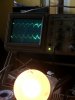
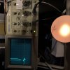
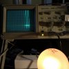
Here are some P/S voltages and images of ripple current coming of rectifier diodes and at big caps. Schematic at bottom of page.

Main caps look like this. +\- 23.8Vdc, Almost 0.2 vac ripple
B6FD31B0-8A20-4ED7-A1DC-14BB238C1C63.jpeg

Top trace: D19/D22 99Vdc, 2.0Vac Ripple
Bottom: C130B (120V) 83.5Vdc, 0.1Vac Ripple.
CAEA82BE-02A0-4341-AF61-79EBD65EEB7E.jpeg

Top: D21/D20 -50Vdc, 0.7Vac Ripple
Bottom: C128B (-43) -30.5Vdc, 0.1mV Ripple
4E23D2B2-4E8C-4440-83B4-0B5F6A6E0DFF.jpeg

other points:
(105V) 70V, 10mv ripple
(90V) 62.3V, 5mv ripple
Q39-E (75v) 69.5

upload_2021-1-22_17-31-6.png
 
Register to hide this ad
You definitely need to put the right value resistor in that R197 location, that power supply is depending on the voltage drops across those resistors to hit the right supply voltages that follow.

The unit is spec'd to draw 70W at the low end, so that'd explain why the bulb is lit. I'd say you're on the right track and can power without the dim bulb. You might step up to 100W, 125W bulbs and be sure it remains good before going without the bulb. I usually walk the bulb wattage up until I can get power cycles where it dims fully after the initial power on before going without it.

That said, it'd be a good idea to wonder why that resistor opened in the first place, and address that first. The C130 multi-cap might be shot, for example.

Good luck,

Bob the Tech
 
I stepped it up to a 150W bulb and all seemed fine after about 30 min. FM plays and lamp element is just lit a low glow. I had tested it with a variable transformer and oscilloscope on outputs, confirmed amp stability on low power startup.
So I went ahead and put it on full 120 line.
Was in AUX and monitoring Bias.
L = 50mv (offset = 31mv)
R = 42mv. (Offset = -42mv)

After a few minutes of just watching at 0 volume I heard a small pop from top side. No smoke released. Put it back on DBT and FM. Now Left FM output is extremely low, AUX is good both sides. Looking in the tube cage I see two tubes uncovered and four covered. All are lit. The top most covered one is noticeably dimmer then the others. The lettering has been obscured by rust/patina so can’t read the tube numbers.
Any guidance moving forward would be much appreciated. Pics below of FM boards.
66A22D29-4751-4EA4-B0D8-B766CA604736.jpeg
C4243868-C36E-48E8-A655-13EFB1F53790.jpeg
2AF288C1-E228-48F6-AA3F-D29228F877BB.jpeg
 
I suggest that a good cleaning and visual inspection top and bottom is a good place to start, given what is visible from above. Next, test all tubes, returning each to their original positions if they pass. As Bob suggested (and strongly seconded by me), replacement of C130 and all the other electrolytics in the power supply (given the age and physical condition of the receiver). You could still have problems beyond the power supply but you wont know until you know it's up to spec.
 
Thanks ramjet, makes sense to me. I tried to check the p/s caps in place and got way off readings. Either their way out of spec or I need to pull them to test properly.
 
Now that I see the condition of that unit I think I'd recommend backing up a step and rebuilding that power supply, replacing those capacitors and checking it all out with no load first. I wouldn't worry too much about the glow bright vs. dim, they'll vary, but testing the tubes is smart. Your pop may have been Q6, 8, or 10 as tuner (and phono) passes through this path while aux does not, the rest of the preamp/amp path is common.

Bob the Tech
 
If this is for a customer as it seems, I would suggest that the customer should understand that the entire unit needs proper service for anything to be guaranteed, and I wouldn’t touch it without the okay to recap and fully service any electrolytic caps and a thorough cleaning.

A patchwork repair is not a good idea IMO on something in its apparent condition.
 
If this is for a customer as it seems, I would suggest that the customer should understand that the entire unit needs proper service for anything to be guaranteed, and I wouldn’t touch it without the okay to recap and fully service any electrolytic caps and a thorough cleaning.

A patchwork repair is not a good idea IMO on something in its apparent condition.
Thanks for the input. I agree fully and have communicated with owner on this point and linked him to this thread to help layout what the situation is with this 1700 and share the opinions of the MAC experts here. He will review this thread tonight and we will discuss tomorrow.

S/N is 37J4
 
Last edited:
Not bad at all. Still doesn't change the need for a recap as it looks untouched from the factory.
 
Now that I see the condition of that unit I think I'd recommend backing up a step and rebuilding that power supply, replacing those capacitors and checking it all out with no load first. I wouldn't worry too much about the glow bright vs. dim, they'll vary, but testing the tubes is smart. Your pop may have been Q6, 8, or 10 as tuner (and phono) passes through this path while aux does not, the rest of the preamp/amp path is common.

Bob the Tech

I finally received new caps (C128, C130, C133) from Hayseed and new filter caps (C132, C132) plus C128 from Mouser and installed these yesterday. Sure hope the Hayseed's are wired same as old ones. I did give them all the specs and I measured each to make sure I had them installed correctly. Have not powered up just yet. I wanted to ask about this fried resistor I found coming off of T5 of IF/MPX circuit. After studying the schematic I believe it was R125 (68 ohm) connected to ground at end of C160. I am a bit confused with C160 as it is not listed in the parts BOM. Is it the connector that is inserted in the shielding? Anyway, wondering if it may have been the tick or pop I heard described in post #3 above that took out Left FM output.

See pic below. I replaced with a 68ohm 1/2W FP resistor. Wondering if it just went short when put on full 120V or something else caused it to burn in half previously. Trying to read the markings looked more like a 64 ohm. But I only had a 68 and that’s what is on schematic. Hoping that is close enough.
333063DA-88F3-458F-BD53-B079108ACDB1.jpeg A4B24DDF-95A7-42B7-9BA1-AB2F67D65BCE.jpeg

I also found a resistor lead R44 2.2K ohm that was not soldered down on the top. It is between tied to output to Tuning Meter and GND. Probably explains why Tuning Meter was not working.
95C8FCE1-FAB3-479E-8E8A-2459D8976CDD.jpeg

Anything else I need to beware/aware of before I bring it up on variable transformer and DBT and no load?

Pic of circuit around T5:
MAC1700 IF-MPX T6 area.jpg
 
Last edited:
C53 and C160 are feedthrough filters, they might be somewhere else in the bill of material.

I'm looking at that schematic and trying to figure out why that resistor would be smoked, and all I can think is that there is an issue upstream that's getting some voltage on there that shouldn't be there. I'd poke around to see if anything looks wrong. Is C49 in good shape or is it shorted, which would pass 116 V to the output side of T5 and potentially down to R125. Is T5-3 shorted to T5-6? What's coming in from below, at number 14 C53. Are R40, 41, 42 in good shape?

What I'd do if I had reworked the supply is try to remove or isolate all the loads and bring it up to ensure the supply is building voltages that look appropriate, and then connect loads and check biases.
 
C53 and C160 are feedthrough filters, they might be somewhere else in the bill of material.

I'm looking at that schematic and trying to figure out why that resistor would be smoked, and all I can think is that there is an issue upstream that's getting some voltage on there that shouldn't be there. I'd poke around to see if anything looks wrong. Is C49 in good shape or is it shorted, which would pass 116 V to the output side of T5 and potentially down to R125. Is T5-3 shorted to T5-6? What's coming in from below, at number 14 C53. Are R40, 41, 42 in good shape?

What I'd do if I had reworked the supply is try to remove or isolate all the loads and bring it up to ensure the supply is building voltages that look appropriate, and then connect loads and check biases.

Thanks for the input Bob. I'll check what you suggested and report back. Currently here is where I stand functionally. Still on DBT w/75W bulb.
Brought up on variable transformer watching DCV on speaker Terminals. Seemed fine. Only thing noticeable was the Left side did not rise as much as the right size. Left ramps up to 3.2 vdc and then ramps down to about -0.6 vdc then back to 0 quickly. Right side peaked about 2.5 vdc and dropped to about -0.5vdc very briefly before immediately back up to zero. All before 30 vdc supply voltage.

On the DBT with 75W bulb it brightens slightly then settles to a low medium brightness. More than all solid state units I'm used to working on but I assume the tube section draws a bit more power.
Here are my Power Supply voltages with no load and flat controls on the DBT:
Mains C131-132 (+/- 37) = +/- 24.1 (65%)
120V C130B = 88.5 (73.7%)
105V @ C130C = 73.7 (70.2%)
90V @ C130D = 65.3 (72.5%)
-43V @ C128B = -30 (69.7%)
75V @ Q39-E = 72.6 (96.8%)
35V @ C133B = 34.3 (97.4%)
10V @ C134 = 99.7 (97.4%)

I pulled each tube and tested for continuity. All passed. Wiped the pins with a bit of deoxit F5 on q-tip before reinstall each one.
Amp offset and bias was adjusted previously but have not hit that yet. Is it safe to power up on full mains? I'm being cautious.
I had previously cleaned the control pots and switches several weeks ago.
All other switches and pots working OK.
All indicator lights working. Note: MPX light stays lit at all times.

AUX Input working
Tape Monitor (intermittent operation if jiggled) working.
Have not tested Phone 1/2 yet.
FM Auto: Not getting any sound passed to either speakers w/300ohm flat T antennae connected (Was previously getting both channels before, until pop took out Left side on full power).
Tuning Meter does not move with tuning. Stays in same position just left of center regardless of power state or tuning.
 
While checking around I found another burnt resistor. Can’t believe I missed that earlier. looks like R37 (220) running between T5 pin4 and T4 Pin 3.
Here is pic of area. R37 circled in yellow.
BBA568B0-9560-4CE6-ACC2-CDA843180547.jpeg
Close up view:
E006ADD9-1754-414C-8551-892BDB714AD3.jpeg
 
Last edited:
I replaced R32 with a 220 ohm 1/2W Flame Proof resistor (NEC) that I had. Did not find any other components that looked burnt. Checked the items Bob mentioned above and didn't find anything out of the ordinary. R40 (22K) measured 17.6K in circuit, but that has a cap C51 (Ceramic tube) so I discounted that reading. I did not lift a leg for further testing.

Tested power on with Variac and seems to pass the ramp up test. Put on DBT 60W = OK then 75W. I got the FM output to BOTH speaker now after a minute of warmup. Still running on 75W DBT. Is it time to try full power yet?

Current issues:
1. MPX light staying lit at all times
2. Tuning meter still not moving.
3. Muting On cannot get any FM reception to pass.
3. Tuning off to the left on the lower side of dial.

Will test Phono1 & 2 later tonight.
 
Rolled the dice and put on full line power...No Smoke! :banana:
This cleared up the MPX light issue, It is now operating properly if tune or detune an FM signal or switch inputs.
Tuning meter moving if ever so slightly off center if detuned. I'll check that out.
FM Muting still cuts all FM.
Tested Phono 1 and it is working.

Issue #1: In Stereo Mode the Left output is 80% lower than Right for FM and Phono inputs. in Mono they are equal.
AUX/TAPE Inputs are working properly. I will trace this down with schematic and O-Scope. Possibly Q6 or Q10 on Preamp board based on Block Diagram.
Hopefully a little more patience and will get all the kinks worked out.
 
Update: I found C149 (100uf, 12V) was shorting R101 (1.8K) down to 32 ohms. When I was de-soldering one leg came off completely. I have new Vishay (TE) caps for both boards and the Output Driver boards I was planning to replace once I verify this resolves my issues with FM/Phono/Tape Head signal through Left Channel. Putting new Caps on Left Preamp channel today.

I did pull Q6 and Q8 (2N4250) and they tested good although Hfe was not close. Question: Should I reuse them or replace with KSA992FBU?
 
Just to close this thread up:
After replacing the bad C149 with a new Vishay (TE) axial cap I confirmed the Left PreAmp is now passing equal level as Right. I then recapped both PreAmp Boards with same Vishay (TE) series axial caps. I used WIMA Film MKS2 1.5uf caps on the coupling caps C110/C111 of PreAmp. Also the e-caps on Driver boards. Most were well out of spec.Everything working properly.Bias dials in at 40mA. I going to open another thread on distortion on the Driver board when operating the Tuner.
 
Back
Top Bottom