• The move to the new server is done. There are some software and database maintenance updates in process. This has us passing the hat around to help out. We appreciate any donations. Seriously, even a dollar helps. The payment page may be found here - https://www.audiokarma.org/support.html

MAC 1900 replace output transistors 132-080, 081

Jon Weston

New Member
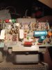
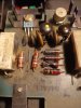
IMG_20230410_233024.jpg IMG_20230410_233048.jpg Hello folks,

Need help/advice.

I finally got around to fixing the left channel output board on my MAC 1900 (serial:8X588, so no substitutions from notes 8-12 in service manual). The 132-081 transistor, one MJ15003, two BC416C epitaxial trans., And four carbon comp. resistors we're fried. Finally got the (mostly) NOS replacement parts, installed them (A970BLs, the suggested replacement for BC416Cs, have "C" and "E" reversed, which caused a little confusion), turned on the receiver at min volume with a pair of Sansui SP-2500s in main speaker, and my phone plugged into Tape-1 via RCAs....

....and☁️
R429, R425, and R431 spontaneously combusted, scorching and blistering the 132-080 Motorola transistor (Q411)

Sooo...

replaced all that, turned it back on and... ☁️

No actual flames this time, or visible damage to Q411, but R421 R423 R431 all fried almost instantaneously. Whether scorched by adjacent frying resistors, or frying themselves, R425 and R427 looked pretty charred.

I can't really signal trace without turning it on, but everything seemed as kosher as a multimeter could determine.

Does anyone know, can I run this thing with the left channel output card removed? with the right card plugged into the left channel slot?

Any other diagnostic methods or ideas about what's wrong?

Any advice greatly appreciated

Jon Weston.

Edit

(I forgot to mention: The PREAMP -> AMP bridges, metal "U"s, were in place in the back for the first turning-on fire, removed for the second one. Don't know whether that eliminates any possible suspects, but seems like it should)
 
Last edited:
Register to hide this ad
Your posting this in the tuner forum. Topics here are radio related. Sounds like you are having amplifier issues. I'm going to move this over to the MAC forum.
 
In your initial post you only mention replacing one MJ15003 (output) transistor, and seem to refer to the 132-081 as an output transistor, which it isn't. The very commonest cause for parts getting fried on these boards are one or both output transistors (132-070) shorting out. If one shorts out, always replace both, and it is nearly always a good idea to replace other semis ahead of them in the circuit-- drivers, predrivers, differential pairs, etc. Why? Because when an output shorts, a very high current is then drawn through much the circuit, and that causes stresses in the parts that may cause them to weaken, if not fail outright.

Did you change both output (MJ15003) transistors, or only one? Also, check to be sure that the power supply rail fuses have not been replaced with more than the normal values, 5 amperes in this case. For testing purposes, you can reduce this value temporarily to provide some safety on the initial power-up, say perhaps 2 amps.

Speaking of fuses, why didn't they keep the damage from occurring? One, a fuse a a last-ditch protector in most cases when you are dealing with semiconductors-- it's a race against time whether the fuse opens, or-- the device fails. The fault current has to flow through both, after all. Also, your model likely has what is commonly called a "crowbar" speaker protector, which, when it detects the presence of a DC voltage on the output circuit, literally shorts the output to ground, with the idea of blowing the fuse(s) before the amplified DC can damage your speakers. (The idea is to possibly sacrifice the power transistors to save the speakers.)
 
Nothing more to add except that the both transistors (yellow dot 132-021 and orange dot 132-032 ) need to be replaced (even if they look fine ) because there is many problem because of them . The perfect sub are MPSA55 and MPSA05 just take a great care of the way to connect EBC for the new transistors (Beware of NPN and PNP)
These boards are really simple to refix so you will not get any difficulties
 
And replace both those original electrolytic caps! That was one of the first things I did on my 1900.
 
In your initial post you only mention replacing one MJ15003 (output) transistor, and seem to refer to the 132-081 as an output transistor, which it isn't. The very commonest cause for parts getting fried on these boards are one or both output transistors (132-070) shorting out. If one shorts out, always replace both, and it is nearly always a good idea to replace other semis ahead of them in the circuit-- drivers, predrivers, differential pairs, etc. Why? Because when an output shorts, a very high current is then drawn through much the circuit, and that causes stresses in the parts that may cause them to weaken, if not fail outright.

Did you change both output (MJ15003) transistors, or only one? Also, check to be sure that the power supply rail fuses have not been replaced with more than the normal values, 5 amperes in this case. For testing purposes, you can reduce this value temporarily to provide some safety on the initial power-up, say perhaps 2 amps.

Speaking of fuses, why didn't they keep the damage from occurring? One, a fuse a a last-ditch protector in most cases when you are dealing with semiconductors-- it's a race against time whether the fuse opens, or-- the device fails. The fault current has to flow through both, after all. Also, your model likely has what is commonly called a "crowbar" speaker protector, which, when it detects the presence of a DC voltage on the output circuit, literally shorts the output to ground, with the idea of blowing the fuse(s) before the amplified DC can damage your speakers. (The idea is to possibly sacrifice the power transistors to save the speakers.)

So now I have 2 new mj15003s on the left (problem) channel, and replaced the burned resistor(s) and re-oriented the A970BLs which I replaced the BC?416s with. Is that a kosher substitution? I can't find where I heard that when I ordered the A970BLs. The specs seem...like it should work, now that I snapped out of the dyslexia that had B, C, and E....confused. (E is opposite of a 416, with the package rotated 180deg, B and C need to switch places as well)

I then started checking everything with the digital multimeter I borrowed (had only analog needle gage before, so no checking the 22 ohm and 33 ohm resistors etc. very closely with that)

The digital multimeter was skittery as ____. Very hard to get any kind of stable, consistent reading. By comparing the good and bad output board....they at least seemed to skitter in parallel . Eventually I began checking the far right lead...trace or whatever it's called, where the board plugs into the slot, red lead of the multimeter on #1 according to the service manual, black on #2, then #3, then #4 etc. All of these were close to identical until #6, which leads directly to the "metal can" or TO-72 transistor, which is ID'd in the service manual as a diode (D414), but spec'd as an epitaxial planar "N channel junction FET".

D413 on the good output board seemed to have 80ohms resistance across it (two leads are twisted/connected...gate and source?)

D414 on the problem board is shorted/0.3-1.1ohms.

I can find no other deviation between the two boards. Some post here on AK spec's that transistor as a 2N5245
, but there does not seem to be any with a similar "metal can" package new or NOS, just TO-92. Does anyone know if is this a good replacement? Should I replace both of the original, metal package transistors (L D414, R D413) at the same time, or does it matter?

More importantly, does anyone have an inclination as to whether that shorted transistor could have been causing the resistor in the attached picture to flame out less than a second after power on? One lead of 132-079, a driver transistor, goes directly to that resistor. Does D414 control that (enough volts coming through 132-079 to fry a 10ohm resistor) somehow? The ...driver transistors?....including 132-079 seem unharmed.

Just trying to get up the nerve to turn it on again

 
So now I have 2 new mj15003s on the left (problem) channel, and replaced the burned resistor(s) and re-oriented the A970BLs which I replaced the BC?416s with. Is that a kosher substitution? I can't find where I heard that when I ordered the A970BLs. The specs seem...like it should work, now that I snapped out of the dyslexia that had B, C, and E....confused. (E is opposite of a 416, with the package rotated 180deg, B and C need to switch places as well)

I then started checking everything with the digital multimeter I borrowed (had only analog needle gage before, so no checking the 22 ohm and 33 ohm resistors etc. very closely with that)

The digital multimeter was skittery as ____. Very hard to get any kind of stable, consistent reading. By comparing the good and bad output board....they at least seemed to skitter in parallel . Eventually I began checking the far right lead...trace or whatever it's called, where the board plugs into the slot, red lead of the multimeter on #1 according to the service manual, black on #2, then #3, then #4 etc. All of these were close to identical until #6, which leads directly to the "metal can" or TO-72 transistor, which is ID'd in the service manual as a diode (D414), but spec'd as an epitaxial planar "N channel junction FET".

D413 on the good output board seemed to have 80ohms resistance across it (two leads are twisted/connected...gate and source?)

D414 on the problem board is shorted/0.3-1.1ohms.

I can find no other deviation between the two boards. Some post here on AK spec's that transistor as a 2N5245
, but there does not seem to be any with a similar "metal can" package new or NOS, just TO-92. Does anyone know if is this a good replacement? Should I replace both of the original, metal package transistors (L D414, R D413) at the same time, or does it matter?

More importantly, does anyone have an inclination as to whether that shorted transistor could have been causing the resistor in the attached picture to flame out less than a second after power on? One lead of 132-079, a driver transistor, goes directly to that resistor. Does D414 control that (enough volts coming through 132-079 to fry a 10ohm resistor) somehow? The ...driver transistors?....including 132-079 seem unharmed.

Just trying to get up the nerve to turn it on again

...and of course, thanks to classic_CJ for the rundown. I don't seem to be able to blow the one fuse I can locate (on the back, labeled "fuse", next to the power cord. ) Are the others you mentioned in some inaccessible recess I have not yet gotten into?

Is it worth getting NOS or salvaged replacement ceramic disc caps, or do the new ones work indistinguishably? It's hard to tell in-circuit. I know ceramic caps don't wear out/go bad like electrolytics, but a couple are pretty black from repeated resistor fires adjacent to them.
 
Back
Top Bottom