• The move to the new server is done. There are some software and database maintenance updates in process. This has us passing the hat around to help out. We appreciate any donations. Seriously, even a dollar helps. The payment page may be found here - https://www.audiokarma.org/support.html

Maggie Console Rebuild: Chapter 1: The Premise

Cathode Resistance

The plate/cathode current is just the cathode voltage divided by the cathode resistance using Ohm's Law (I = V/R).

Using the MPX schematic. Each tube diagram has a voltage going in. In this case the 6AB4 has 2.5V. Using the table in the schematic it says I should get 1000 ohms at the cathode. 2.5/1000=.0025A ~2.5mA.

Using this same idea the 6EU7 would be 2*(1V/1000ohms)=2mA

Is this correct?

Likewise, is this an accurate measure of the current demand in the power supply? Are there any other sources eating up significant amounts of current that need to be accounted for in the calculations?
 
Actually we can figure the load of the tuner very easily. Just measure it. Break the B+ feed to the tuner and stick your multimeter in there set to MA. It will read the current flow to the tuner directly. No need to make this more complicated than it has to be, its a simple measurement to obtain.

If you want to see total current load of the amplifier, you can do the same thing, but breaking the feed between the first capacitor and everything downstream of it. Keep in mind that thats just static draw, when you wind up the loud knob it will peak higher. If you want to know just the power output stage, measure voltage across the cathode resistor and divide that by the value of the cathode resistor. Thats your output tube idle current in amps. Shuffle the decimal as needed to make it into a useful value.
 
Is this correct?

Likewise, is this an accurate measure of the current demand in the power supply? Are there any other sources eating up significant amounts of current that need to be accounted for in the calculations?

Yes, that is the basic idea, however due to the wide parts tolerance in tube amps and fluctuations of the mains voltage, etc., the actual figures are going to deviate from the ones shown in the schematic, but they should be close enough for govenment work as some say... or you can follow gadget's suggestion and perform the acutal current draw measurements.
 
Actually we can figure the load of the tuner very easily. Just measure it. Break the B+ feed to the tuner and stick your multimeter in there set to MA. It will read the current flow to the tuner directly. No need to make this more complicated than it has to be, its a simple measurement.

Forgive me, but, will that work? The power switch is in the tuner. So by pulling the umbilicus I won't be able to get a hot reading.
 
Loving The Learning

Just want to throw in a thanks to everyone participating in this discussion.
I'm loving the learning, I just wish I could retain things like I could at 22.
 
Measuring Tuner Current Quandary

The weeds grow quickly...

Sometimes you have to unsolder or cut wires to break a circuit for a meter reading.

Im going to have to wait until I'm actual into the guts of the MPX and tuner to figure out how to measure. I'm working with several different schematics and the molex patterns don't seem to match up. I'm going to have to do some continuity testing to figure out which line is which.
Also, I've got to sit down and go step by step through the ps chain to see where to test. I guess immediately after the switch. Power goes from amp to the MPX to the tuner. Then from the switch embedded in the treble control to the TT. Then back to power up the MPX. It's absolutely fricken insane.
I think I just talked myself through it.
If I pull the molex out of the TT I can measure upstream current demand. Yes!
Please tell me I'm correct!
 
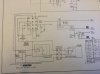
Picture of Tuner Power Supply Circuit

Pic of ps circuit.
 

Attachments

  • image.jpg
    image.jpg
    56.8 KB · Views: 18
Actually we can figure the load of the tuner very easily. Just measure it. Break the B+ feed to the tuner and stick your multimeter in there set to MA. It will read the current flow to the tuner directly. No need to make this more complicated than it has to be, its a simple measurement to obtain.

Where do I need to attach the negative lead on my mm? Does this work like voltage and just go to ground? Thanks.
 
Looks like pin 3 on that socket tells you what you're looking for.

Are you referring to the tuner plug molex? The 40mA on the 250V line?
Or the bottom (3rd pin) on the phono plug?

I've isolated the line that goes from the TT through the bottom pin in the phono plug and back to the MPX at pin 8 of the tuner molex.

I was going to cut it between the TT and phono plug and complete the circuit with my MM. Nice easy spot for a simple wire lug repair while I'm working through the rest of the console.

Unless the 40mA on the schematic is what I've been looking for all along.
 
Current Quandary Solved

From that one photo that's what I'd take it to be. As long as that 250v source line is the only place the tuner/MPX gets any high voltage from the B+ then you can read that as providing 40ma to it.

Okay, current demand for the console should be easily handled. ~130mA for the amp and 40mA for the tuner. That's ~170mA. I should be fine with the ~225-250 mA provided by a 5AR4 rectifier. Once I break into the actual construction I'll verify these figures with actual readings.

That said, to use a 5AR4 I would need to up the first cap to ~60/450 per the data sheet, and calculate the drop resistor value to get the B+ down to keep the 6EU7s happy.
 
Power Supply Rectifier Decision Time

Okay, I believe that it has been established that the 5AR4 can provide enough current to keep everything moving and will provide additional voltage to improve output performance.

While working this out here, I have a pm conversation going on the side with battradio about converting to the SS ps mentioned by Levane earlier in the thread.

It's Power Supply Rectifier Decision Time:

Two questions to anyone with an opinion.

1.) Is the marginally increased voltage from the rectify switch actually going to improve output performance. Several of you have made this change. Is it efficacious or not worth the price of a new tube?

2.) Does switching to SS rectification have any impact on the audio character of an amp. I understand that if I want super stable and quiet that SS is the way to go, but will it change the sound?
 
Why the desire for the 5AR4

H,

What exactly is your reason for going to a 5AR4? Give me specific power numbers that have you going for this.

This is mostly driven by the rectifier/voltage discussion that went on in fasterdamnit's thread "mighty magnavox 9302 finally goes ultralinear" and referencing the voltages used in the Dynaco ST35 amp using a similar UL circuit as I'm working on creating here. Dynaco went much hotter than the 325 to center tap that my 9304-20 w/5U4GB provides. In fasterdamnit's thread it was discussed that there is an inherent power reduction/loss with UL. I don't believe the loss was quantified or necessarily explained(I've done a ton of reading lately, all blending together). Upgrading to a 5V4 or 5AR4 was discussed at length. I haven't included the 5V4 in my inquiry because of its lower current yield.

Hopefully going to build this only one more time, so trying to optimize things on the front end.
 
To Increase Voltage or Not To Increase Voltage?

Higher B+ is only usefull if you plan on running the volume high enough to be past 1/2 power in output watts, giving the occasional bass notes than might pull full power out of your amp the chance to rattle your windows. Is that what you need? As for the lower output power of UL it won't be noticable because of the power to dB factor. Will you be running full volume much? The 9304 is a 15W/channel amp in standard pentode mode and the ST-35 is how much more? 2W? You also have a higher B+ just from the line voltages being higher today than when the amp was designed for 117v.

I'd say the answer is no. Or very rarely. My wife hates loud music, my older kids hate my music, and I'm hardly ever alone in the house without my 8 year old. Even then I typically find about half way up the loudness dial to my liking.
 
Current/Voltage Question Solved

Half way up the volume is about 2 W. Maybe 3....:banana::banana:

So between 6DZ7s dancing bananas:banana::banana: and what I finally just found online, I think it has been resolved that more voltage is not necessary for my application.

From the Mullard EL84 spec sheet power output per channel is as follows.

Pentode - 17w
20% UL - 15.4w
43% UL - 11 w

That's a 9% loss in the application I plan to use.
For a 9% loss I don't think I need to make any adjustments to the rectification of the power supply. The 5U4GB will be more than suffucient.

Awesome.
 
I'd be inclined to leave the rectifier alone as well. I changed mine because I had one, but I wouldn't have bought a tube. I may change it back, I've got a box of 5U4GB's and not a single spare 5ar4 or 5V4. The slight power loss from UL is not really significant. Running the tubes closer to design center ratings will make them last longer too, and thats likely something that will be more measurable.

and yeah, if you want to measure the tuner, break the wire going to pin 3 and wire the meter in as an ammeter. Or just use the 40ma number handily provided on the schematic :) Its probably close enough to go by.
 
Power Supply Decisions: Pricing Out SS vs Tube

Have you thought about a SS power supply? I went that route with my 9304 and it turned out great! I think I have a drawing for a SS PS for this amp for UL.

Lavane, I took a look at your build. And as I've been discussing how a SS power supply would work for my build.

I'm set now on either sticking with the 5U4GB or possibly converting to SS rectification. I've been assured that I can get similar stability out of either system if built right.

I'd like to price out each to see what it would cost both ways to help make the decision.

Can you share where you sourced the 470uf lytics and diodes you used for your build?

Thanks
 
Sorry it took so long, packing for a trip. :D I got the 470uf 450v 35mm caps from eBay. But you should be able to get them from Mouser or digikey. The diodes I used were Uf4007's also from Mouser. The .1uf and .047uf bybass caps from capacitor world. They have an add banner here on AK. You will want to get a small assortment of 2-3watt resistors to adjust the voltage. 10 ohm worked for the first one but I had to use a 27 ohm for the last one. I ordered the choke from Angela. They have a nice assortment of Hammond chassis too.
 
Back
Top Bottom