• The move to the new server is done. There are some software and database maintenance updates in process. This has us passing the hat around to help out. We appreciate any donations. Seriously, even a dollar helps. The payment page may be found here - https://www.audiokarma.org/support.html

Magnavox 142 - rebuild/modification thread

No and yes!

Okaay, what gives? What's next?

The altecs and tis amp are truely incredible together. :drool::drool::drool:


I don't even have mon out on my preamp, so I am only getting half stereo right now and it is still really good. :music::music:

I am going to go and start stripping hte next one, get it ready to assemble.


Fun, fun, fun, and more fun!
 
Okaay, what gives? What's next?

The altecs and tis amp are truely incredible together.

Are you still having 0D3 problems? Have you made sure the inverter is balanced? Is the first triode biased high enough for full output without clipping? Is the resistor still paralleled with the choke? Nothing to keep you from enjoying the amp but things that should be addressed at some point.

I'm looking forward to hearing it though!
 
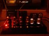
here is a picture of her running.

I wish there was a way to dim the pilot a little.Any suggestion on what resistor and how to wire it? Series or parallel?

Mark
 

Attachments

  • P1010066.jpg
    P1010066.jpg
    66.6 KB · Views: 66
It is running as it should. No resisitor paralleled, no 0D3 issues until it gets really loud. I think it is running excellent right now.
 
The first tubes bias should be fine, no issues there.

I like the voltages in the amp pretty well, would still play with the regulator section
and verify how things are running, but it looks pretty decent as is, ah phase splitter
balance, I don't have a great 6SL7 spice model so I can't say for sure but what I've
got with the voltages now present in that amp it balances really well with an 18K in
for the 20k in the split grid to ground resistor, but without a perfect tube model and
not having those exact 6SL7's(others will be different when you plug them in) I can't
say how close it would be, my gut says use 18k if your not checking or "adjusting" it.

But if he's getting good results on the scope maybe leave well enough alone, build #2.. :thmbsp:
 
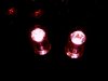
here is a pic of the 0D3. I couldn't get it to look as nice as it does. it has a really cool glowing cloud inside.
 

Attachments

  • P1010071.jpg
    P1010071.jpg
    25.2 KB · Views: 45
Gotta love those VR tubes..:yes:

(just a tweak)
If your going to do anything with the 2 47k resistors paralleled for the front end RC
stage I'd suggest using a single 4.7k there, 1w is more then fine, should get you oh
100v at that plate of the first tube, 157v at the second, 1.5v on that first cathode
and 2.5v on that second cathode, just a little more voltage to perk things up there.. :)
 
ok, I'll replace the 20k with an 18k.

As to the two 47k paralleled(23.5k), replacing with a 4.7k, is this correct? I ask becuse it is a failry large change. If it is correct, It will be done too.


Is there a way to measure the current through the PS tranny? A way to determine if the amp is pushing the tranny too hard?

I ran the amp for about 2 hours on a comfortable listening level - probably less than a watt output. After that time the tranny was fairly warm. You could touch it and hold your hand on it, buit it was uncomfortably warm.

Just asking if I should be checking anything?

Mark
 
After 2 hours the tranny is about as hot as it's gunna get, it's pretty normal
to be quite quite warm to the touch, if you can hold your hand on it, should
be just fine, if you can't hold your hand on it is time to worry.

-----------------

As to the 4.7k resistor, yes 4.7k, there isn't a lot of current on that front end
so an change in resistor value doesn't make a drastic change in voltage there.

-----------------

As to the 18k verse 20k resistor, can you do me and Scuzzer a favor? And do
an AC voltage measurement on the splitter, set the amp up testing like you do
for the scope, put enough signal in at say 1k to get between 5-10v ac on one
of the output tube grids, then measure both and tell us what you got in there.

We need to know which is which, in other words according to your schematics
which one is the top tube and which is the bottom tube so we can adjust that.

Also if you have 3 6SL7 tubes can you do this an all 3 tubes, that should tell us
how much variance there is and whether we need to make it "adjustable" or not.
 
After 2 hours the tranny is about as hot as it's gunna get, it's pretty normal
to be quite quite warm to the touch, if you can hold your hand on it, should
be just fine, if you can't hold your hand on it is time to worry.

-----------------

As to the 4.7k resistor, yes 4.7k, there isn't a lot of current on that front end
so an change in resistor value doesn't make a drastic change in voltage there.

-----------------

As to the 18k verse 20k resistor, can you do me and Scuzzer a favor? And do
an AC voltage measurement on the splitter, set the amp up testing like you do
for the scope, put enough signal in at say 1k to get between 5-10v ac on one
of the output tube grids
, then measure both and tell us what you got in there.

We need to know which is which, in other words according to your schematics
which one is the top tube and which is the bottom tube so we can adjust that.

Also if you have 3 6SL7 tubes can you do this an all 3 tubes, that should tell us
how much variance there is and whether we need to make it "adjustable" or not.


The splitter? I think you are refering to the 20k/220k resistor junction?

Output grids? Pin 4 of the 6v6gt's? - correct?

Both? Both what? Input voltage and grid votlage? Both the upper nad lower 6v6gt? Both halfs of the 6sl7? Sorry, I missed what you'e asking.

As to multiple 6sl7's, I have maybe 6-8 of them. I'll try them once I know what ot measure and post back.

Mark
 
The splitter? I think you are refering to the 20k/220k resistor junction? (yes that's part of the splitter adjustment)

Output grids? Pin 4 of the 6v6gt's? - correct? (pin 5 is the grid/input, measure ac voltage there with 1k signal at the amps input)

Both? Both what? Input voltage and grid votlage? Both the upper nad lower 6v6gt? Both halfs of the 6sl7? Sorry, I missed what you'e asking.

(The AC grid voltage on both the upper and lower 6v6 grids, with the 1k AC signal generator at the amps input)

As to multiple 6sl7's, I have maybe 6-8 of them. I'll try them once I know what ot measure and post back.

Mark


The answers are in bold..
 
What a phase splitter does in a push pull amp is try to get an even amount of signal
to the 2 tubes in the push pull output pair, so we want to see the AC voltage at the
grids of both output tubes, if it is not even then we need to adjust that 20k resistor.

To check this we need to put an AC signal into your amp, just like you did to look at
your amp on the scope, look to get between 5v and 10v AC on the 6v6 pin 5 to set
your input level from the generator, then measure both the upper and lower 6v6 AC
grid voltage, that will tell us how balanced the splitter is.

Don't adjust the input for each grid, set it once then measure what is at both grids.
(then shut the amp down, then turn back on with another 6SL7 an repeat/measure)
 
Here's a thought you might kick around regarding the phase inverter and it's balance issue: Convert it from it's present status as a simple paraphase inverter to a floating paraphase inverter. This would be very simple to do, and would cause the inverter to automatically balance regardless of what particular tube is used in the inverter position.

To make the conversion, the grid return resistor for the top set of output tubes should be increase from 220K to 240K. Then, R5 (originally 20K), should be increased to 100K. Finally, un-ground the grounded end of the grid return resistor for the bottom set of output tubes, and connect it to the junction of the upper output tube grid return resistor and the new value R5 resistor. That's it.

With the new configuration, the signal supplied to the bottom inverter grid now contains an error signal that automatically causes the inverter outputs to remain in balance, regardless of what tube might be used. It may need very slight tweeking, but the balance should be very close with these simple changes -- and likely much closer than the original design ever was.

In addition, the previous suggestions to reduce the inverter plate resistors to 220K is excellent. It's never a good idea to have plate resistors greater in value than the following stage grid resistors. Reducing them to 220K puts them on par with the grid return resistors for the output stage. In addition, reducing the value of the 100K B+ dropping resistor for the inverter stage is also an excellent idea. I would target a B+ operating voltage in the range of about 270 vdc for the inverter stage when all is said and done. Both of these moves will increase the drive quality and capability of the inverter stage significantly.

With these changes, and assuming the inverter has been changed to a floating type design, I would also reduce both cathode resistors for the inverter tube to 2.7K. This would allow proper linearity for the new operating parameters, and also allow the stage to produce the increased drive it is now capable of.

Also -- and again assuming conversion to a floating type design -- I would bypass the bottom inverter section's cathode resistor with a small 20 mfd cap like the upper section's cathode resistor is. This will further maximize inverter performance, and help insure balance regardless of actual inverter tube balance or condition.

Finally, when bias voltage versus peak input voltage is examined for the top inverter section, be sure to include the peak value of the NFB voltage inserted into this section in the calculation. This voltage adds on top of the dc bias present to make up the total bias for the tube under full power conditions. With the values shown, the peak value of the NFB voltage is over .90 volts from the 4 ohm tap, and 1.30 volts from the 8 ohm tap (if that is where the FB is taken from), based on a full power output voltage of 12.24 vac rms from the 8 ohm tap. In either case, this puts the total bias for the top inverter tube at least at 2.20 volts. Therefore, since the peak value of the full power input signal was less than 2.0 volts, it's unlikely the inverter stage was clipping when operating in its original form.

Dave

 
okay,
here is the scoop

First, I replaced the 47k with a pair of 10k in parallel - so I now have a 5k resitor in that spot.

I tested six 6sl7. I set the tester up and adjust the output on the frequency generator to 1k and 7.02volts on pin 5 v2.

tube v2 v4
1 7.02 9.78
2 7.03 9.54
3 7.03 9.65
4 6.97 9.69
5 6.82 9.35
6 6.99 9.72

So, what does this mean?
 
Here's a thought you might kick around regarding the phase inverter and it's balance issue: Convert it from it's present status as a simple paraphase inverter to a floating paraphase inverter. This would be very simple to do, and would cause the inverter to automatically balance regardless of what particular tube is used in the inverter position.

To make the conversion, the grid return resistor for the top set of output tubes should be increase from 220K to 240K. Then, R5 (originally 20K), should be increased to 100K. Finally, un-ground the grounded end of the grid return resistor for the bottom set of output tubes, and connect it to the junction of the upper output tube grid return resistor and the new value R5 resistor. That's it.

With the new configuration, the signal supplied to the bottom inverter grid now contains an error signal that automatically causes the inverter outputs to remain in balance, regardless of what tube might be used. It may need very slight tweeking, but the balance should be very close with these simple changes -- and likely much closer than the original design ever was.

In addition, the previous suggestions to reduce the inverter plate resistors to 220K is excellent. It's never a good idea to have plate resistors greater in value than the following stage grid resistors. Reducing them to 220K puts them on par with the grid return resistors for the output stage. In addition, reducing the value of the 100K B+ dropping resistor for the inverter stage is also an excellent idea. I would target a B+ operating voltage in the range of about 270 vdc for the inverter stage when all is said and done. Both of these moves will increase the drive quality and capability of the inverter stage significantly.

With these changes, and assuming the inverter has been changed to a floating type design, I would also reduce both cathode resistors for the inverter tube to 2.7K. This would allow proper linearity for the new operating parameters, and also allow the stage to produce the increased drive it is now capable of.

Also -- and again assuming conversion to a floating type design -- I would bypass the bottom inverter section's cathode resistor with a small 20 mfd cap like the upper section's cathode resistor is. This will further maximize inverter performance, and help insure balance regardless of actual inverter tube balance or condition.

Finally, when bias voltage versus peak input voltage is examined for the top inverter section, be sure to include the peak value of the NFB voltage inserted into this section in the calculation. This voltage adds on top of the dc bias present to make up the total bias for the tube under full power conditions. With the values shown, the peak value of the NFB voltage is over .90 volts from the 4 ohm tap, and 1.30 volts from the 8 ohm tap (if that is where the FB is taken from), based on a full power output voltage of 12.24 vac rms from the 8 ohm tap. In either case, this puts the total bias for the top inverter tube at least at 2.20 volts. Therefore, since the peak value of the full power input signal was less than 2.0 volts, it's unlikely the inverter stage was clipping when operating in its original form.

Dave

Hey Dave, Quite a laundry list, and something Iwill do. Sound great. Ill post some results when I get it done.

Now that the circuit is getting close to "tweaked", how would I measure this for performance. I can get the watts out at clipping easy enough. But is there any thing else I can do? Is there anything you would like to see? I can take pics of wave forms or measurments or???

Mark
 
Right next to the input jack on the schematic above. The schematic shows a 12AX7 so on it it would be pin2 but on your amp the input grid is pin 1. Perhaps someone needs to redraw the schematic so that it shows what's actually in your amp.

edit: I'll be right back.

I deleted the one above and changed the pinouts for the 6SL7. I might have it correct. If you jot down what is different on your amp I'll make the changes to the schematic so we all know what we're talking about when make suggestions.

magnavox142rev2.jpg

Hey GAry,
I was going in to redo the schematic/ redraw it and I noticed you had done it all. Thanks!
I thought you only did the input section on this. I owe you another one.

Mark
 
Last edited:
OK as suspected the 20k resistor is to high an the balance is off. (R5)

Replace the 20k with 15k should just about be right where we want it.
(or parallel a 56k across the 20k that is in there)

---------------

Dave's suggestions are great, I have built versions of that, but I'd really
like to get this version nailed down first if we could, it would help out my
tube models an we can put this as a tweaked/adjusted working schematic.


okay,
here is the scoop

First, I replaced the 47k with a pair of 10k in parallel - so I now have a 5k resitor in that spot.

I tested six 6sl7. I set the tester up and adjust the output on the frequency generator to 1k and 7.02volts on pin 5 v2.

tube v2 v4
1 7.02 9.78
2 7.03 9.54
3 7.03 9.65
4 6.97 9.69
5 6.82 9.35
6 6.99 9.72

So, what does this mean?
 
OK as suspected the 20k resistor is to high an the balance is off. (R5)

Replace the 20k with 15k should just about be right where we want it.
(or parallel a 56k across the 20k that is in there)

What do you think of Dave's suggestions? I can do either.

Mark
 
Back
Top Bottom