• The move to the new server is done. There are some software and database maintenance updates in process. This has us passing the hat around to help out. We appreciate any donations. Seriously, even a dollar helps. The payment page may be found here - https://www.audiokarma.org/support.html

Magnavox 175 upgrade to Hammond 1620A OPT question.

Tommyd2k

New Member
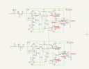
I have a pair of Hammond 1620a"s on the way. The amp is a 185 with the 7025 removed, all caps and resistors replaced and coupling caps upped to 0.1 and 0.01. Sounds great, I just want to give it 8ohm taps and some more range. I sketched out how I think it should be wired, but I would appreciate any feedback before I go ahead and install them. In the schematic I used the UL taps, but I will probably use them without at first, then compare later.
Mainly I want to make sure the feedback loops are correct. Since they were wired to 4ohm taps, I just copy that?
Screenshot 2026-09-03 000210.png
 
Register to hide this ad
Feedback networks are generally specific to a given transformer model, so a change to a different model transformer will at minimum likely require some adjustment for optimal use. Wiring the same circuit to the 4R taps should give a similar amount of feedback, but the compensation will likely need adjustment. It's possible it sounds ok, it's also possible that it behaves poorly without adjustment.
 
Don't forget to separate the output tube cathodes between R & L channels.

Use 250 ohms 5w for each pair and a 100 uf 100V Bypass capacitor.

:)
 
honestly if you're doing this, I'd seriously consider reworking the driver section to Dave's work from the 8800. There are notes in there specific to the 175, but it converts the driver to a floating paraphase design which improves performance, and alters bias points to make it all work better.
 
Don't forget to separate the output tube cathodes between R & L channels.

Use 250 ohms 5w for each pair and a 100 uf 100V Bypass capacitor.

:)
I was thinking of using 500ohm per tube. With the added benefit of a convenient point to test individual tube bias. In that case, what value cap?
Feedback networks are generally specific to a given transformer model, so a change to a different model transformer will at minimum likely require some adjustment for optimal use. Wiring the same circuit to the 4R taps should give a similar amount of feedback, but the compensation will likely need adjustment. It's possible it sounds ok, it's also possible that it behaves poorly without adjustment.
I assume this has been covered as it relates to this transformer. I will have to do some searching to see what others have found works.
honestly if you're doing this, I'd seriously consider reworking the driver section to Dave's work from the 8800. There are notes in there specific to the 175, but it converts the driver to a floating paraphase design which improves performance, and alters bias points to make it all work better.
I'm a newbie to all this. Thanks for the tip. I will look into this.
 
per-tube cathode resistors tends to have worse performance since there is no self-regulation. As one tube draws more current the other draws less, so overall the cathode voltage remains more stable.
 
per-tube cathode resistors tends to have worse performance since there is no self-regulation. As one tube draws more current the other draws less, so overall the cathode voltage remains more stable.
OK. So if I go with 250k on each resistor I can add a 1ohm to each for a test point? I sketched it out below
 

Attachments

  • Screenshot 2026-09-03 184937.png
    Screenshot 2026-09-03 184937.png
    71 KB · Views: 5
Last edited:
You don't need the 1 Ohm as you can read the voltage across the 250 ohms and calculate current.

I'd rather let two well matched tubes fight it out than four at once as the Factory did.
 
^ this, if you're adding a DC balance pot then it would need something to sample across but really you should have decently matched in a channel of a push-pull amp.

The stock setup has a slight advantage when doing single channel driven measurements, but its really small in a 6V6 amp since they run basically class A and have very little shift in current from idle to full scream. Makes a difference in an AB amp though. More practically it was done to save a cap and a resistor.
 
Back
Top Bottom