• The move to the new server is done. There are some software and database maintenance updates in process. This has us passing the hat around to help out. We appreciate any donations. Seriously, even a dollar helps. The payment page may be found here - https://www.audiokarma.org/support.html

Magnavox 9302 - Rebuild

Cameron06

New Member
I recently acquired a Magnavox 9302, and I'm in the process of rebuilding it. I've stripped the chassis completely, and I'm nearly done doing the mechanical work on the chassis... soldered over the extra holes, body filler, all the aesthetic stuff.

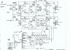
I'm having some trouble with the schematic, though. Everything I've found on here is very low-resolution, and most of the schematics I see have some modifications. I've put together my own schematic based on the original with a few major differences:
A few of the components from the original schematic have different values based on the model. Right now, this has no model number; I'm building it from the ground up with new components. The only items I'm keeping are the choke and the chassis. That being said, this is what I'm trying to figure out:
  • R112 / R109 - Since I don't know the difference between each model of the 93-series, I'm not sure what values to use for reference. Additionally, since R112 is the feedback resistor from the output stage, does it change things since I'm wiring it for ultra-linear mode? I have read than in UL mode, feedback is often not necessary. Is there any truth to this?
  • R117 - I'm using a balance pot, and one of the schematics I'm referencing has a 300-ohm resistor from either leg of the pot to ground; this isn't part of the original schematic. What's the purpose of this, and do I need it?
  • Pre-amp Tubes - I'm swapping the 6EU7s for 12AX7s. Other than the different pinout and heater wiring, should I be aware of anything?
  • Output Transformers - I'm willing to trade power for frequency response, so I want to build this in UL mode. Other than wiring the screens into the output transformer screen tap instead of +300V, are there any recommended modifications?
I've already ordered the transformers, but anything else can be changed as-needed. I have a fair amount of experience designing and building electronics, but mostly with digital, and never with tubes. I really appreciate any advice or criticism (hopefully the constructive kind). I don't know anyone personally who can double-check my work, unfortunately.

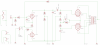
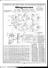
I've attached the two schematics I'm using for reference as well as my own schematics (9302-Power and 9302-Audio). The volume control is missing from my schematic, but it should otherwise be complete.

(If it makes any difference, this will be fed from a Little Bear T11 phono preamp swapped with 12AX7 tubes; this has a volume control and a very hot output at high volume. For now, at least, it will be powering a set of Polk Ti500 speakers @ 8ohms with a sensitivity of 91dB).
 

Attachments

  • Mag9302MSMods (1).jpg
    Mag9302MSMods (1).jpg
    138.9 KB · Views: 183
  • correct9302.jpg
    correct9302.jpg
    46.7 KB · Views: 173
  • 9302-Power.png
    9302-Power.png
    153.5 KB · Views: 150
  • 9302-Audio.png
    9302-Audio.png
    115.1 KB · Views: 156
Register to hide this ad
Welcome aboard @Cameron06 !

I recently acquired a Magnavox 9302, and I'm in the process of rebuilding it.... I have a fair amount of experience designing and building electronics, but mostly with digital, and never with tubes... I really appreciate any advice or criticism (hopefully the constructive kind). I don't know anyone personally who can double-check my work, unfortunately.

Sounds like you have a good concept of what you're doing and where you want to go with it.

I've attached a link that has become the de-facto guide and pretty much indispensable when it comes to working on 93XX series amps.

The author of the thread is one of thee main go to guys here when it comes to tube amp builds/rebuilds/mods etc. which I believe he can do in his sleep:D

It's a long a read but the first several pages get to the meat of the matter so hopefully you'll find it helpful.

We like pictures here, clear and detailed the better so if you have questions or as you mentioned someone to double-check your work please post pics along with questions.

https://www.audiokarma.org/forums/index.php?threads/more-fun-with-magnavox-the-9300-series.687735/

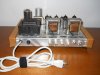
Here's one I had done several years ago, they really sound good.

DSCN0118.JPG
 
I've attached the two schematics I'm using for reference as well as my own schematics (9302-Power and 9302-Audio). The volume control is missing from my schematic, but it should otherwise be complete.

Nice work! ...

I notice that in your amplifier 9302-Audio schematic you are missing the cathode ground for the output tubes between R114 and R115.
 
If you would like a branch off Dave's original thread with HF tuning that may be more appropriate to those Edcor transformers, this may be what you're after. Note the model number is not precisely the same, so I can't absolutely guarantee the HF tuning is going to be identical but I suspect it should be in the neighborhood at least. The schematic in post 20 is what I ended up with.

https://audiokarma.org/forums/index.php?threads/magnavox-9300-with-edcor-cxpp25-ms-8k-iron.754809/

Mine is built using the original Magnavox power transformer, so you'll have to work out any differences in the supply for yourself. Honestly unless the stock one was bad, there isn't a lot of reason to replace it. Its overkill for what is asked of it.
 
Welcome aboard @Cameron06 !


Sounds like you have a good concept of what you're doing and where you want to go with it.

I've attached a link that has become the de-facto guide and pretty much indispensable when it comes to working on 93XX series amps.

The author of the thread is one of thee main go to guys here when it comes to tube amp builds/rebuilds/mods etc. which I believe he can do in his sleep:D

It's a long a read but the first several pages get to the meat of the matter so hopefully you'll find it helpful.

We like pictures here, clear and detailed the better so if you have questions or as you mentioned someone to double-check your work please post pics along with questions.

https://www.audiokarma.org/forums/index.php?threads/more-fun-with-magnavox-the-9300-series.687735/

Here's one I had done several years ago, they really sound good.

View attachment 2249109

Thanks for the information and the welcome! I've already been browsing that thread you linked quite a bit, but I think I really need to take some time to read through it thoroughly again. Speaking of pictures, I did post pictures of my schematics, but unfortunately I don't have much to post of the amp itself, unless of course you feel like looking at photos of a stripped-down chassis and an unfinished wood case. :) Your amp looks great, BTW. I like the red inlays you used in the miter joints.
 
If you would like a branch off Dave's original thread with HF tuning that may be more appropriate to those Edcor transformers, this may be what you're after. Note the model number is not precisely the same, so I can't absolutely guarantee the HF tuning is going to be identical but I suspect it should be in the neighborhood at least. The schematic in post 20 is what I ended up with.

https://audiokarma.org/forums/index.php?threads/magnavox-9300-with-edcor-cxpp25-ms-8k-iron.754809/

Mine is built using the original Magnavox power transformer, so you'll have to work out any differences in the supply for yourself. Honestly unless the stock one was bad, there isn't a lot of reason to replace it. Its overkill for what is asked of it.

I don't think the stock transformer was bad, but physically it's in pretty sorry shape; to be completely honest, I wanted something that was nice to look at. The output on my power transformer is exactly the same as the original with the exception that there's no second 6.3V winding, which wasn't needed anyway. I agree that the tuning should be similar; it looks like you're using the same OPTs that I am, with the exception that mine have a 23% tap. At the very least, it should give me a good baseline to start from. Thanks!
 
@gadget73 - After reading over Dave's thread, it looks like there's a lot to be gained by using an LM337 and his EFB setup. I've gone over your schematic that uses Edcor transformers, and to be honest, I think I'll probably end up duplicating it almost exactly. I had planned to use the 23% taps on my transformers for UL, but at this point, I think I'd rather try the EFB configuration and leave the taps disconnected.

I did want to ask you, though, it looks like you added another preamp stage using 1/2 of a 6EU7 before the main preamp. My plan so far has been not to add this extra preamp stage, although I've seen others do it. Did you add this primarily to fill the extra opening in the chassis, or did you find that more preamp gain was necessary?

I really appreciate fact that you and others on this forum are willing to share your work. It's really a lot of help for newbies like me.
 
Same here however a friend of a friend who is pretty good working with wood whipped that up for me.

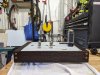
@Dswankey I just finished the case for mine today. Probably not as fancy as yours, but I'm mostly happy with it. I'd have preferred do to some better joinery, but since the front and back have to be thinner material to fit the connectors through, it was just easier to do butt joints and dowels for reinforcement. I suppose I could have done dovetails or box joints, but I'm lazy. I really want to finish and paint the chassis, but until I can mount the transformers and figure out where to drill holes, that's on hold until Edcor decides to send them to me.

The tubes in the pictures aren't connected... just old ones to show what it will look like when done.
 

Attachments

  • PXL_20210606_022152006.jpg
    PXL_20210606_022152006.jpg
    130 KB · Views: 86
  • PXL_20210606_022159086.jpg
    PXL_20210606_022159086.jpg
    125.3 KB · Views: 85
^ Looking good!!!, curious though it looks like you wrapped around the back.

Here's a visual of the back on the one I posted earlier also note the rubber feet

DSCN9927.JPG
 
@gadget73 - After reading over Dave's thread, it looks like there's a lot to be gained by using an LM337 and his EFB setup. I've gone over your schematic that uses Edcor transformers, and to be honest, I think I'll probably end up duplicating it almost exactly. I had planned to use the 23% taps on my transformers for UL, but at this point, I think I'd rather try the EFB configuration and leave the taps disconnected.

I did want to ask you, though, it looks like you added another preamp stage using 1/2 of a 6EU7 before the main preamp. My plan so far has been not to add this extra preamp stage, although I've seen others do it. Did you add this primarily to fill the extra opening in the chassis, or did you find that more preamp gain was necessary?

I really appreciate fact that you and others on this forum are willing to share your work. It's really a lot of help for newbies like me.

Its a cathode follower that doesn't actually produce any gain. Its not strictly necessary but if you want to add a volume control it can be useful since you won't have any HF loss from Miller effect across the volume control. The resistance of the volume control plus the effective capacitence of the stage makes a low pass filter, so at lower levels on the volume control it can chop the highs out. The buffer has far less capacitence so that becomes mostly not a problem.

I can't claim inspiration for it, Dave's final draft with the Dynaco iron added it as well.
 
^ Looking good!!!, curious though it looks like you wrapped around the back.

Here's a visual of the back on the one I posted earlier also note the rubber feet

View attachment 2250228

Yes, it covers all 4 sides. The panels on the front an back are significantly thinner than the sides, so I don't think I'll have much trouble fitting the connectors through. There are no holes yet; still have to buy the connectors.

I'm planning do to the same things as yours with the rubber feet.
 
Its a cathode follower that doesn't actually produce any gain. Its not strictly necessary but if you want to add a volume control it can be useful since you won't have any HF loss from Miller effect across the volume control. The resistance of the volume control plus the effective capacitence of the stage makes a low pass filter, so at lower levels on the volume control it can chop the highs out. The buffer has far less capacitence so that becomes mostly not a problem.

I can't claim inspiration for it, Dave's final draft with the Dynaco iron added it as well.

Ah, I understand now; thanks for clearing that up. Looks like I was also referencing an old version of Dave's schematic (2015), vs the one you based your design off of from 2017. I'm still not sure if I want to add volume control or not since my photo preamp already has a volume control built-in.
 
@gadget73 If you don't mind, I had one more thing I wanted to ask you. I have a 500k dual pot that I want to use for volume control. I'm a bit confused, though, since everything I've read about this is based on the original schematic. In yours/Dave's, there is a 470k resistor between the input signal and the .01uF capacitor another 470k resistor from this capacitor to the outer case of the RCA jack/GND. How would you fit a potentiometer into this? I'm thinking I'd replace the 470k signal resistor with the pot and wire the wiper on the far side of the 470k ground resistor. Does this sound right?
 
The two 470k resistors are there mostly as a voltage divider to make it less sensitive. With those in place it wants 1.3 volts for full output, without those resistors it would be half that so 0.65v. If you fit a pot in there you can ditch both resistors. Top of the pot to the RCA jack, bottom to ground, wiper to the 0.01 cap.

If you didn't want a pot you could still eliminate that 470k from RCA jack to the 0.01 cap in order to make it more sensitive. I left it alone since without it the volume control on my preamp ends up barely cracked and too sensitive. The ratios of those resistors can also be meddled with in order to adjust input sensitivity.
 
The two 470k resistors are there mostly as a voltage divider to make it less sensitive. With those in place it wants 1.3 volts for full output, without those resistors it would be half that so 0.65v. If you fit a pot in there you can ditch both resistors. Top of the pot to the RCA jack, bottom to ground, wiper to the 0.01 cap.

If you didn't want a pot you could still eliminate that 470k from RCA jack to the 0.01 cap in order to make it more sensitive. I left it alone since without it the volume control on my preamp ends up barely cracked and too sensitive. The ratios of those resistors can also be meddled with in order to adjust input sensitivity.

Oh, that's a voltage divider! I hate to admit, but I didn't even realize that. I have always seen them drawn with one resistor over the other tapped off between the two; it didn't quite "click" when I saw them drawn parallel. Thanks again.
 
@gadget73 I just noticed that on your schematic with the Edcor transformers, you're biasing your output tubes at 15mA. Looking at Dave's schematic using the stock transformers, he's doing 44mA per channel, so 22mA per tube. Did you find that the tubes perform better at 15mA with the Edcor OPTs? I've been trying to research the "best" bias for an EL84, but everything I'm seeing is in the context of guitar amps, and I'm not really interested in how my amp will perform when it's over-driven; ideally it never will be.

For now, the amp is almost done. Unfortunately I still have to wait for probably a lot longer before Edcor decides to ship my transformers.
 
Thats just where the distortion bottomed out, or at least I'm assuming thats why I did that. I remember talking with Dave about how to determine the right bias point with EFB, and if I remember that conversation right it basically came down to looking at the output on a distortion analyzer and wherever it bottomed out was the right spot. Why exactly mine came out different than his, I don't know. Different tubes perhaps, or maybe different power levels. I think I was running EL84M tubes when I worked that out, its possible that the Sylvania set I have in there now would come out slightly different.

I really suspect you could run it anywhere from 15 - 25ma and not notice any obvious difference in performance or tube life.

Best is really dependent on the circuit. If this were standard cathode bias, the magic spot would likely be considerably higher. Generally with hifi stuff the bias point is chosen for minimal distortion and not exceeding tube ratings. EFB happens to work in such a way that the optimal point might be well below tube ratings.
 
Back
Top Bottom