• The move to the new server is done. There are some software and database maintenance updates in process. This has us passing the hat around to help out. We appreciate any donations. Seriously, even a dollar helps. The payment page may be found here - https://www.audiokarma.org/support.html

Magnavox A9304 amplifier project

Going to post here because I also recently obtained a very similar unit.

Thread specifically for mine: https://audiokarma.org/forums/index.php?threads/finally.997912/

----

Basically, now I'm totally confused. Stick with the 6EU7's or rewire for 12AX7's?

Use the original (apparently poor) Phase Splitter design or go with a more standard Cathodyne arrangement as above?

Note that's at least 4 possible combinations, not counting specific Cathodyne circuits.

If I rebuild mine using a Direct Coupled 12AX7 arrangement like I've used in my other builds, then it's probably going to sound just like stuff I've made before. I'm not going to learn anything new about other configurations.

I'm sorry I'm not the expert here I'm just a old worn out radio operator / repair man...

Have you read @dcgillespie more fun with magnavox 9300 series thread yet?

https://audiokarma.org/forums/index.php?threads/more-fun-with-magnavox-the-9300-series.687735/

All the important information is in the first four pages.... Dave is highly respected and I would recommend reading it... His designs are very highly recommended by others here... Page 4 has his two wrap up posts that contain the diagrams and all the details of his modified design... I'd recommend at least reading the first four pages closely it's a very long 75page thread...

I'd recommend at least bucking the power transformer like Dave did with the spare radio heater coil to save your tubes from the higher line voltage of today... Other than that I really couldn't say...

scan0003.jpgSAM_1574.JPG.jpg

Nice to meet you and best of luck to you...

Don
 
EFB can be applied to a lot of things though. I have a console amp that started life as a Madison-Fielding unit, now its got transformers from a Hammond tone cabinet, some cheap old Soviet tubes that aren't used in much of anything, and an EFB regulator. The EFB concept is his idea, but the implementation is entirely my fault.

Did I misunderstand you? Is that circuit design that @FlaCharlie posted your work? Wow...

Don
 
Not my work, I just mentioned that having EFB doesn't mean its Dave's work either.


Use the original (apparently poor) Phase Splitter design or go with a more standard Cathodyne arrangement as above?

The stock one kind of sucks, but the revised floating paraphase works pretty well. One advantage you get out of a paraphase or floating paraphase over a cathodyne is minimal heater-cathode voltage difference. The cathodes run at a couple of volts so there isn't any need to consider bias on your heater string to keep it from beating up the insulation. That might be the only advantage if I'm being honest, but I'm following Monty Python's advice and looking on the bright side of life.

One thing that does confuse me about paraphase vs floating parapase designs though, its really just a matter of moving one resistor to make it work. I don't know why they aren't all floating designs, its not more complicated or more expensive to implement.
 
Not my work, I just mentioned that having EFB doesn't mean its Dave's work either.


The stock one kind of sucks, but the revised floating paraphase works pretty well. One advantage you get out of a paraphase or floating paraphase over a cathodyne is minimal heater-cathode voltage difference. The cathodes run at a couple of volts so there isn't any need to consider bias on your heater string to keep it from beating up the insulation. That might be the only advantage if I'm being honest, but I'm following Monty Python's advice and looking on the bright side of life.

Very good Points...

Engineering is kinda beyond me some of the time stuff makes complete sense but it isn't entirely right ... So no unsourced unproven circuits...

I realized I'm just a old kid still learning new things playing with big boy toys and enjoying life as much as I can...

I'm hoping that the new power transformer gets here today.

The 12ax7 to 6eu7 adapter arrived yesterday and it didn't work with the tube tester... But the tube works with the adapter in my other Magnavox amplifier just fine... I'm calling the 6eu7 tube alive...

I have a sovtek 6eu7 coming... So if it works mostly the same way I am set for now...
 
might depend on how your tester does the 12ax7. If they run it in 12v mode, it won't work with a 6eu7. It has to run the tube in 6v mode.
 
I used the 6.3v setting for the filiment... the FC tube tester owners manual came in handy. I dunno I'd have to look inside the adapter...
 
what I mean is it depends on how they apply power. If its from 4 to 5, it won't work. That would be 12v mode, so if thats what the tube tester calls for using with a 12ax7, thats why it doesn't work with a 6EU7 in the adapter.

If the tester has you use 6.3v for a 12ax7 then it should work. That would be 4&5 tied together to one side of the supply and 9 to the other.
 
One advantage you get out of a paraphase or floating paraphase over a cathodyne is minimal heater-cathode voltage difference. The cathodes run at a couple of volts so there isn't any need to consider bias on your heater string to keep it from beating up the insulation. That might be the only advantage if I'm being honest, but I'm following Monty Python's advice and looking on the bright side of life.
I really know zilch about the technical advantages / disadvantages of the different varieties of phase inverters.

But, as I recall, one of the other characteristics of the paraphase is that they have some gain, whereas other types do not or may even reduce the gain slightly. So in some situations that might be helpful.

I have no idea how much the use of the paraphase inverter contributes to the sound, but at some point I realized that many of the vintage amps I enjoy listening to the most use it. So I've never hesitated to use it in DIY projects, whatever technical shortcomings it might have.

When I built my modded Magnavox 175 /185 I used a floating paraphase inverter that I copied from the $3500 Leben, which has a very loyal and enthusiastic following.

https://www.audiokarma.org/forums/index.php?threads/magnavox-175-185-build-with-a-twist.934198/

As far as I can tell, the Leben is really just a modern version of the Magnavox 9300 with high quality OTs.
 
I used the 6.3v setting for the filiment...
what I mean is it depends on how they apply power. If its from 4 to 5, it won't work. That would be 12v mode, so if thats what the tube tester calls for using with a 12ax7, thats why it doesn't work with a 6EU7 in the adapter.

If the tester has you use 6.3v for a 12ax7 then it should work. That would be 4&5 tied together to one side of the supply and 9 to the other.
I'm guessing that most testers use 12.6v but perhaps there's a workaround . . . see if the tester has a setting for the 6AX7. A 6AX7 uses 6.3v between pins 4 and 5 (series) and 3.15v between 4&5 tied and 9 (parallel). Otherwise, it's the same as a 12AX7.
 
Last edited:
Should be able to configure the tester for the correct pins. Just a matter of knowing what the switches are doing. I have been able to DIY a configuration or two on my Hickok for tubes that weren't in the charts.
 
I'm guessing that most testers use 12.6v but perhaps there's a workaround . . . see if the tester has a setting for the 6AX7. A 6AX7 uses 6.3v between pins 4 and 5 (series) and 3.15v between 4&5 tied and 9 (parallel).

that wouldn't work either. A 12ax7 to 6eu7 adapter would need to feed power from 4/5 to 9, not from 4 to 5.


I really know zilch about the technical advantages / disadvantages of the different varieties of phase inverters.

But, as I recall, one of the other characteristics of the paraphase is that they have some gain, whereas other types do not or may even reduce the gain slightly. So in some situations that might be helpful.

I have no idea how much the use of the paraphase inverter contributes to the sound, but at some point I realized that many of the vintage amps I enjoy listening to the most use it. So I've never hesitated to use it in DIY projects, whatever technical shortcomings it might have.


sort-of yes, sort-of no on the gain. A paraphase has the gain of the first triode. The second triode has gain too, but since the input is knocked down in order to get the same output voltage as the first triode it really doesn't count.

A cathodyne in and of itself is slightly under unity. What you get from grid to ground will be a wee bit more than you get from plate to ground or cathode to ground. Its usually paired with another tube as a voltage amp stage, so you still get the gain of the first tube. Overall it ends up not that different in terms of total gain than a paraphase once you figure in the two sections.

The problems with the paraphase are largely about the balance of the two sections and how it varies with frequency. On the bottom end, you get the coupling cap reducing signal to the inverter as the frequency goes lower. On the top end, you get the Miller effect in the tube causing some roll-off in the voltage divider that feeds it. If you ever set one up on the scope and balance it perfectly at 1khz, you can watch it go out of balance as you shift the frequency up and down. Tubes aren't perfect either so even if you get the balance perfect at one spot with one tube, changing tubes may shift it some.

The floating paraphase is also sometimes called a paraphase with feedback. At least thats what the RDH calls it, since thats more properly what it is. Basically by moving where the ground connection is, you get some local feedback at the tube that goes a long way towards making sure the output is actually equal no matter what the frequency is.

The Valve Wizard -Paraphase

has some more technical stuff about the two of them.

Cathodynes don't have the variable response issues, they just need matched resistors and you get balanced output. The down side being the cathode runs at a bunch of volts so H-K voltage is something that needs to be considered. On the up side, since that also means the grid needs to be a bunch positive, it makes direct coupling a possibility. Eliminating a cap between the voltage amp and inverter removes one possible phase shift point so you have less places to cause instability in the amplifier. Fisher used this with 12ax7 tubes, but you can also find the triode/pentode tubes set up this way in Dynaco and plenty of other gear.

diff pair / long tail pair amps also have gain, but its basically the same as a single triode would be. They also tend to have very good balance, though if you don't size the grid to ground cap properly it can get unbalanced at lower frequencies. Same problem with heater-cathode voltages, and also the same potential for direct coupling.

as for why you'd use one over the other, frankly I don't have an answer to that. Only things I've ever changed has been a paraphase to a floating paraphase and thats kind of like putting better tires on the car you already have. I have amps with cathodynes in both direct coupled and cap-coupled config, and one with a direct coupled long tail pair. They all sound fine but different. Wouldn't care to guess how much of the difference is the inverter and how much is the fact that nothing else is the same between them either. Too many variables to even try and figure that out.

 
Thanks for the explanation. It seems like the floating version of the paraphase is pretty much on par with the other options from a technical standpoint.
 
It's gotta be something simple the adapter and 6eu7 works in the Magnavox 175-67

There's a 6ax7 setting... I had the tester setup right for it... I'll figure out what is up with it later... Thank you...

The new power transformer arrived and I installed it this afternoon... It didn't take as long as I thought it would to install...

IMG_20220609_170804.jpg IMG_20220609_170847.jpg

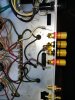
I also removed the speaker connectors and soldered in the new binding post/banana jacks...

IMG_20220609_170900.jpg

It's dinner time for Buddy the mule and me... I'm late with his groceries..
 
Well I must be getting better because I couldn't sleep last night...

So I got a few more things done...

I removed the RCA jacks... And covered the opening...

IMG_20220610_071133.jpg IMG_20220610_071243.jpg

I wired and soldered in the new RCA jacks...

IMG_20220610_071254.jpg

I repaired a few spots on the wiring... And melted all the original solder connections that weren't being changed... Just in case...

I cleaned up the metal some more to get my dirty fingerprints off the metal it's starting to look like I wanted...

12 resistors left to go...

IMG_20220610_072630.jpg
 
I took a cat nap to compensate for being up all night working on the amp... And when I woke the wife said I have a package...

I'd just received a gift in the mail from my best friend and mentor the luthier Matt...

He's always sending me bits of his old stuff that won't do for his business anymore to encourage me to practice and ply my trade

A box of cloth wire...

IMG_20220610_134037.jpg

Today's treasure 3 12au7 tubes

IMG_20220610_133717.jpg

This is inspirational to me and has triggered many advances in my hobbies building guitar, playing music and electronics too...

A box with bags of kits of famous peoples guitar harnesses...

IMG_20220610_134914.jpg

This is why I'm building him a Magnavox amp... He says that repairing old amplifiers is out of his skill set and expressed jealousy over the 175-67 I rebuilt with you guys help.

I believe that the 175-67 is right one to send him because of that comment alone...

there is other reasons why I think this other module is better...

a odd off hand comment here about The 175-67 design by Dave about it being the model that needed the least mods to the original circuit to sound good...

This a9304 doesn't have the original transformer...

There's some issues with the stock a9304 design on the ocilliscope...

I don't want to send Matt a very custom circuit in case it needs worked on by someone other than me...

But I use the 175-67 daily as my little home PA for music practice... So as soon as this one is working I'm pulling 175-67 out of the console shell and finishing it's pretty stuff wooden skirt and RCA jacks polishing...

And sending it to him... I'll feel way better when it's done and in his hands...

Don
 
I really know zilch about the technical advantages / disadvantages of the different varieties of phase inverters.

But, as I recall, one of the other characteristics of the paraphase is that they have some gain, whereas other types do not or may even reduce the gain slightly. So in some situations that might be helpful.

I have no idea how much the use of the paraphase inverter contributes to the sound, but at some point I realized that many of the vintage amps I enjoy listening to the most use it. So I've never hesitated to use it in DIY projects, whatever technical shortcomings it might have.

When I built my modded Magnavox 175 /185 I used a floating paraphase inverter that I copied from the $3500 Leben, which has a very loyal and enthusiastic following.

https://www.audiokarma.org/forums/index.php?threads/magnavox-175-185-build-with-a-twist.934198/

As far as I can tell, the Leben is really just a modern version of the Magnavox 9300 with high quality OTs.

you have a much better grasp of this stuff than I do... being able to combine multiple designs into something else is a skill I set I don't really have yet...

Fixing a circuit yes... copying a circuit yes... Adding the necessities to modify a amplifier to stand alone yes... More than that I'm still struggling...

Don
 
that wouldn't work either. A 12ax7 to 6eu7 adapter would need to feed power from 4/5 to 9, not from 4 to 5.


sort-of yes, sort-of no on the gain. A paraphase has the gain of the first triode. The second triode has gain too, but since the input is knocked down in order to get the same output voltage as the first triode it really doesn't count.

A cathodyne in and of itself is slightly under unity. What you get from grid to ground will be a wee bit more than you get from plate to ground or cathode to ground. Its usually paired with another tube as a voltage amp stage, so you still get the gain of the first tube. Overall it ends up not that different in terms of total gain than a paraphase once you figure in the two sections.

The problems with the paraphase are largely about the balance of the two sections and how it varies with frequency. On the bottom end, you get the coupling cap reducing signal to the inverter as the frequency goes lower. On the top end, you get the Miller effect in the tube causing some roll-off in the voltage divider that feeds it. If you ever set one up on the scope and balance it perfectly at 1khz, you can watch it go out of balance as you shift the frequency up and down. Tubes aren't perfect either so even if you get the balance perfect at one spot with one tube, changing tubes may shift it some.

The floating paraphase is also sometimes called a paraphase with feedback. At least thats what the RDH calls it, since thats more properly what it is. Basically by moving where the ground connection is, you get some local feedback at the tube that goes a long way towards making sure the output is actually equal no matter what the frequency is.

The Valve Wizard -Paraphase

has some more technical stuff about the two of them.

Cathodynes don't have the variable response issues, they just need matched resistors and you get balanced output. The down side being the cathode runs at a bunch of volts so H-K voltage is something that needs to be considered. On the up side, since that also means the grid needs to be a bunch positive, it makes direct coupling a possibility. Eliminating a cap between the voltage amp and inverter removes one possible phase shift point so you have less places to cause instability in the amplifier. Fisher used this with 12ax7 tubes, but you can also find the triode/pentode tubes set up this way in Dynaco and plenty of other gear.

diff pair / long tail pair amps also have gain, but its basically the same as a single triode would be. They also tend to have very good balance, though if you don't size the grid to ground cap properly it can get unbalanced at lower frequencies. Same problem with heater-cathode voltages, and also the same potential for direct coupling.

as for why you'd use one over the other, frankly I don't have an answer to that. Only things I've ever changed has been a paraphase to a floating paraphase and thats kind of like putting better tires on the car you already have. I have amps with cathodynes in both direct coupled and cap-coupled config, and one with a direct coupled long tail pair. They all sound fine but different. Wouldn't care to guess how much of the difference is the inverter and how much is the fact that nothing else is the same between them either. Too many variables to even try and figure that out.
Whew that's a lot to digest in one sitting

So paraphrase is a little more unstable than a cathodyne but has a little more gain..

And Cathodynes are more stable but don't have the same Gain is some of what I've gotten out of your post so far...

It seems like it's situational then...

Sometimes I have to read and reread stuff before it makes sense to me...

I bookmarked the link to the valve wizard for more serious thoughtful reading time...

I think Magnavox designs were made to be stable and cheap at the same time with some balance between cost and quality...

These were mostly made to be affordable for the middle ground blue collar worker of the time... I'd say that they did good job and It speaks volumes how popular they still are...
 
Hello - I saw this thread and would like to follow it, however, my Maggie amp is labeled as “9304-20” on the metal chassis (see enclosed pic), and I was wondering if there’s any meaningful differences between my amp and the subject amp in this thread “A9304-00,” especially as mine is missing the letter “A” in front of the name.

9DAAEAAC-6239-4358-836F-7E47ECFFEF19.jpeg4DC43330-BBB8-4DA6-9F07-F79A37978268.jpeg
 
Last edited:
Mine says AMP. 9305-00 to write it in full.

There seem to have been a lot of variations depending on when/where it was built, what tuner/speakers/turntable/etc. was in the console.

Yes, there are also apparently subtle design changes in the actual amplifier.

One of the main variations seems to have to do with the power transformer. It was sized based on what else it powered. Mine PT is noticeably smaller than some of the other ones.
 
Hello - I saw this thread and would like to follow it, however, my Maggie amp is labeled as “9304-20” on the metal chassis (see enclosed pic), and I was wondering if there’s any meaningful differences between my amp and the subject amp in this thread “A9304-00,” especially as mine is missing the letter “A” in front of the name.

View attachment 2589355View attachment 2589357

Same amplifier mostly... welcome to the forum... All are very welcome here...

I see you have the whole console could you possibly please post a picture of the rest of the console...

It's amazing to see one whole to me...
 
Back
Top Bottom