


Carbsandcaps
Super Member
I had a fisher 49t/49a combo which are bulky and awkward as an amp/preamp outside of a console. I decided to use the amplifier separate which isn’t a big project (don’t forget to wire the 12ax7 heater!). This left me with the tuner/ preamp with no power. Instead of harvesting it for parts I decided to make a power supply for it, or at least try. With a lot of help from the people in this community I was able to do it.
I had a transformer with a 350/0/350 output that I figured I could use one leg of but was talked out of it by members on here and rightfully so. I had found 2 heathkit transformers on the eBay’s that powered only preamp tubes so I jumped on them. At the same time someone on here was had found a schematic for the same transformer I just bought! It had 117v and 6.3v outputs which is all that is needed. He had recommended a voltage doubler circuit like the original fisher.
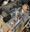
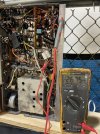
Mounting the transformer was simple enough and for the most part fits on the chassis. Stuffing everything else underneath was another story.
Sorry for my terrible drawing abilities but here’s the diagram.
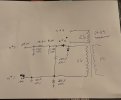
where it says to #1 that’s #1 on the harness that connects the power amp to the preamp. You can cut the wires and pull them back into the chassis and connect them right to the capacitors. It’s basically the same as the original fisher circuit but with 100uf caps (to make up for some lost capacitance) at the end and 220uf caps at the voltage doubler. You’ll see in my case there are a few more capacitors and that’s because I decided to replace the caps inside the can while I was in there. They’re basically shoved wherever I could fit them. The diodes are in the upper corner. The mains were wired to the original switch and a cheap inline fuse holder for safety.
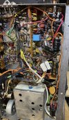

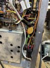
You will also have to rewire the 2 phono 12ax7 and the single preamp 12ax7 heaters by connecting pins 4 and 5 and connecting those 2 pins to one side of the 6.3v feed and pin 9 of the tubes in parallel since they were ran in series with the 24vdc in the fisher design. The swore point might be the 10k ohm resistor. This was needed to get the b+ voltage correct. I used (2) 20k ohm 5 watt resistors in parallel to make the 10k because that’s what I had but it also helps to dissipate better. The resistors never got above 95 degrees so I’m happy with it. The voltage is actually a tad low but I’m ok with that too The transformer also never got hotter than warm to the touch. I also removed the speaker select switch and the auto on switch because they aren’t needed anymore and could use them for future projects.
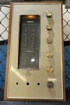
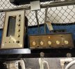
This all makes for a stand alone stereo fisher preamp/ tuner for under $100 (depending on how much you get the preamp for). And let me tell you, this thing sounds amazing! Picks up stations inside the building without an antenna AND has built in multiplex! I’m currently using it at work with my cheapo dewald tube amp and it’s singing sweetly. I may build a case for it but for now its just going to be covered in the bottom with some wood and the face plate is glued on.
I’m sorry I don’t know how to add people’s names to the post otherwise I would because the people who helped with this are owed a great debt of gratitude. If anyone can tell me how to add names I’d appreciate it.
I had a transformer with a 350/0/350 output that I figured I could use one leg of but was talked out of it by members on here and rightfully so. I had found 2 heathkit transformers on the eBay’s that powered only preamp tubes so I jumped on them. At the same time someone on here was had found a schematic for the same transformer I just bought! It had 117v and 6.3v outputs which is all that is needed. He had recommended a voltage doubler circuit like the original fisher.
Mounting the transformer was simple enough and for the most part fits on the chassis. Stuffing everything else underneath was another story.
Sorry for my terrible drawing abilities but here’s the diagram.
where it says to #1 that’s #1 on the harness that connects the power amp to the preamp. You can cut the wires and pull them back into the chassis and connect them right to the capacitors. It’s basically the same as the original fisher circuit but with 100uf caps (to make up for some lost capacitance) at the end and 220uf caps at the voltage doubler. You’ll see in my case there are a few more capacitors and that’s because I decided to replace the caps inside the can while I was in there. They’re basically shoved wherever I could fit them. The diodes are in the upper corner. The mains were wired to the original switch and a cheap inline fuse holder for safety.
You will also have to rewire the 2 phono 12ax7 and the single preamp 12ax7 heaters by connecting pins 4 and 5 and connecting those 2 pins to one side of the 6.3v feed and pin 9 of the tubes in parallel since they were ran in series with the 24vdc in the fisher design. The swore point might be the 10k ohm resistor. This was needed to get the b+ voltage correct. I used (2) 20k ohm 5 watt resistors in parallel to make the 10k because that’s what I had but it also helps to dissipate better. The resistors never got above 95 degrees so I’m happy with it. The voltage is actually a tad low but I’m ok with that too The transformer also never got hotter than warm to the touch. I also removed the speaker select switch and the auto on switch because they aren’t needed anymore and could use them for future projects.
This all makes for a stand alone stereo fisher preamp/ tuner for under $100 (depending on how much you get the preamp for). And let me tell you, this thing sounds amazing! Picks up stations inside the building without an antenna AND has built in multiplex! I’m currently using it at work with my cheapo dewald tube amp and it’s singing sweetly. I may build a case for it but for now its just going to be covered in the bottom with some wood and the face plate is glued on.
I’m sorry I don’t know how to add people’s names to the post otherwise I would because the people who helped with this are owed a great debt of gratitude. If anyone can tell me how to add names I’d appreciate it.
