• The move to the new server is done. There are some software and database maintenance updates in process. This has us passing the hat around to help out. We appreciate any donations. Seriously, even a dollar helps. The payment page may be found here - https://www.audiokarma.org/support.html

Marantz 1060 power amp gets weird when speakers are attached

kevinrontel

New Member
I've been wrestling with this 1060 on and off for a few months. When I acquired it, the left channel was fine; the right channel was always very distorted. After an initial tune-up (cleaned the pots and replaced most of the caps/trannies/diodes), the left channel sill works fine and the right channel is still distorted.

I've isolated the problem to the power amp board--the preamp is fine and everything after the power amp seems to work.

When I run a sine wave into the right channel--but WITHOUT a dummy load (or speaker) attached--the amp sends out a nice looking sine wave into the 'scope.

However, the moment I connect a dummy load/speaker, the bottom half of that wave disappears. I can take before-and-after photos if that'd help.

Adjusting the bias pot and the asymmetrical pot do not fix the issue.

Any ideas what could be killing the bottom half of that signal?

NOTE: When I 'scope both channels using the same input signal, one (presumably the "bad" channel) is inverse to the other.
 
Register to hide this ad
Sounds like one of the right channel output transistors might be bad (not shorted, but defective nonetheless). It won't show up on a basic test, sometimes they fail under a load and cause the symptoms you are describing. I've run into the same issue before on quasi-comp push pull amps, sometimes they will even be fine with headphones but as soon as they are loaded with speakers a weak output transistor can fail. I've even run across amps of this type that will sound fine until the volume hits a certain point and then become a garbled mess. Same thing, one output goes bad and you lose half of the output on that side.
 
You could swap the outputs side to side and see if that isolates the problem. Or if you have new ones, try putting them in on the failing channel.
 
Check for distorted sine wave at
H004base (ie, J712)
H710b

If possible measure H706 Vbe, don't probe the transistor
measure at adjoining part ie, across R732.
 
Check for distorted sine wave at
H004base (ie, J712)
H710b

If possible measure H706 Vbe, don't probe the transistor
measure at adjoining part ie, across R732.

Here are the results of testing. I've revised the part numbers to match the half of the circuit I'm working on.

H001base = Distorted (missing top half of signal)
H709base = Distorted (missing top half of signal)

H705 Vbe (measuring across R731) ~ .019 This roughly matches the Vbe as measured on its left-side equivalent.
---
To mbz and LexDM3: I had previously swapped and checked the output transistors and it appears they're all functional.
 
Was above test with dummy load or speakers connected? Needed to be.
Previously said bottom half was missing at speaker post.
It's probably ok that the bottom half of sine wave is missing on H001, H709, will check.
 
Was above test with dummy load or speakers connected? Needed to be.
Previously said bottom half was missing at speaker post.
It's probably ok that the bottom half of sine wave is missing on H001, H709, will check.

Yep, the test was with speakers connected.

The missing half of the signal seems to switch from top to bottom depending on where I tap into the circuit.
 
Post a pix of the distorted wave form taken at loaded speaker posts.
Is one half completely missing, points to a "break" on that half of the amp
Basic amp working, so probing on the positive/negative half of the amp might
not show other half (neg/pos) of waveform

upload_2019-3-5_13-11-59.png
 
Half wave dissapearing could be caused by a transistor, a burned resistor, or even by a cold solder. Check the power supply rails going to the power amp, each section, check wires are properly soldered or connected, and check any jumper or bridges across PCB traces, and resistors around the output transistors. Make sure the power can reach the output transistors when needed. Sometimes a weak connection makes the amp work, but under a load, when more current is needed, it fails.

The fact you see the signal phase reversed between channels is not normal, check what's happening there, if the same input signal is really 180º out of phase at the output, or if your measuring was not accurate. In case you have the phase reversed, I'd check every single transistor starting at the power amp input, comparing with the good channel, perhaps somebody made a mistake and mixed transistors, NPN instead of PNP, wrong pinout, or any unexpected mistake.

I wouldn't swap parts between the good channel and the bad channel. Keep the good channel working as a reference. If you don't trust some transistor in the bad channel, get a new one, don't desolder parts from the good channel, you can introduce more problems and end with 2 non working channels.
 
Last edited:
Post a pix of the distorted wave form taken at loaded speaker posts.
Is one half completely missing, points to a "break" on that half of the amp
Basic amp working, so probing on the positive/negative half of the amp might
not show other half (neg/pos) of waveform

View attachment 1439450

Here are photos showing...well, the captions should make it clear what they're showing: measurements of the bad channel taken at various points and with and without speaker load.
The signal is definitely getting inverted somewhere between R731 and the output.

I did not include photos to show the respective outputs of both channels, but they are definitely out of phase with one another at the speaker posts.


  • Like
Reactions: mbz
There are just 4 small signal transistors and the 2 drivers before the power transistors. You can always replace all 6 along with the 2 diodes H715 H717. Use the good channel as a reference.

I'd compare voltages at the transistors with the good channel. That usually can narrow the search.

Being an amp bought as non working, so you never had that channel in working condition, I'd replace all diodes and the transistors at once, checking the pinout and checking the resistors too. It will be less than 1 hour work, and you will trust the semiconductors are OK.

I'd use the MAIN IN input, disconnecting the preamp, to discard problems at the preamp (specially that phase problem you have)

Again, check soldering and the connection between the output transistors and the supply voltage. Make 100% sure the power reaches the output transistors, no loose wires, no weak connections.
 
Last edited:
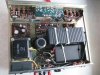
I found some time this week to work on the 1060. After doing a little math (my limited electronic talents + the effort of re-rebuilding one side of the power amp + the time I've already invested in this project), I came to the obvious conclusion: take the shape of your vessel (ie, cheat). I pulled the power amp altogether and, in its place, I stuffed a class D amp I had lying around. Integrity be damned, the amp sounds fantastic, and I've got a giant OCD albatross off my neck.

And, since people keep giving me their old stereo amps ("You've built a few guitar pedals? Here's a non-functioning Yamaha/Fisher/Panasonic/Marantz that's been gathering dust for 40 years!"), I'm gonna continue my Campaign of Vintage Abasement for the foreseeable future.

(After I took the photos below, I pulled the 80V power capacitor, as it wasn't needed; I should probably remove the transformer as well and run everything off a switching power supply. Then again, the amp works. I'm happy.)

Thanks, as always, to all the helpful folks at this fantastic forum.

IMG_2385.JPGIMG_2386.JPG
 
I think you could build your replacement amplifier outside the Marantz cabinet, and later invest some time fixing the original circuit. In my opinion, any vintage Marantz unit worth some effort to keep it running. Even selling it "as is" could be an option..
 
Back
Top Bottom