• The move to the new server is done. There are some software and database maintenance updates in process. This has us passing the hat around to help out. We appreciate any donations. Seriously, even a dollar helps. The payment page may be found here - https://www.audiokarma.org/support.html

Marantz 1060 Rebuild - No Sound Left Channel

tgnadeau

New Member
Hi Everyone;

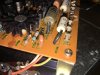
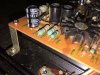
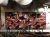
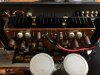
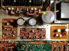
I am looking to get a Marantz 1060 I was able to save working again. When I got it home and powered it up, I found that the left channel was completely dead and the right channel was very low.

Things I've done to isolate the issue:
- Bypassed the power amp- I Bypassed the power amp and found that the phono preamp and the preamp seem to be working okay. (Seems like the power amp board is the issue).

- Tried each input - Each input I've tried is working okay at this time.

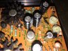
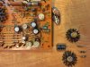
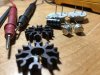
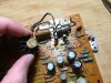
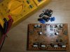
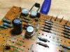
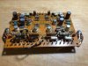
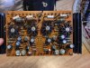
With that information I took the power amp board out so I could start testing components. I found that the following so far:

- C704 - Leaking
- R742 - Blown
- R738 - Blown

I've never done a rebuild of anything like this before, so I've been looking through these threads non-stop trying to gather all the info I can. However, I find a lot of this a bit overwhelming outside of what caps to use for replacements and such.

I'm hoping I can get some recommendations on what transistors to use (Brand etc...). As well as confirm that most likely the 4 driver transistors are bad, and at least the left output transistors are likely bad.
 

Attachments

  • IMG_0194.jpg
    IMG_0194.jpg
    112.5 KB · Views: 79
  • IMG_0241.jpg
    IMG_0241.jpg
    89.9 KB · Views: 76
  • IMG_0242.jpg
    IMG_0242.jpg
    102.7 KB · Views: 71
  • IMG_0245.jpg
    IMG_0245.jpg
    108.7 KB · Views: 74
Register to hide this ad
I am unsure as to the problem with the right channel, perhaps replacing the on board electrolytic capacitors would be a good place to start, ditto with the left.
Before just replacing semiconductors I would try to find out exactly which ones have failed, you can remove them one at a time and test them using the method outlined in echowar's excellent thread.

The blown resistors are an indication of semiconductor device failures in the left channel, there may be other bad resistors that don't show damage.
It is considered 'best practice' to replace the drivers and outputs in pairs, that is, if the NPN driver has failed, replace the PNP driver too, and vise versa. If one output device in a channel has failed, replace the other one in that channel as well.
For driver transistors, 2N5416 (2SA606) and 2N3440 (2SC959) are good substitutes, ST Micro is the best brand, but are getting expensive and hard to find. On-Semi MJ21194G are overkill, but are what I would use for output devices.
H713 and H714 should be replaced with one 1N4448 each.
The AOS transistors, H705-H708, can be removed until all the other issues are solved as long as you don't drive the amp hard without them.
My 2 cents, YMMV

Tom
 
Thanks for the info, it's extremely appreciated.

I cannot find the 2N3440 in anything but Central Semiconductor Corp.

Does anyone have any experience with this Manufacturer? Are they terrible? Is it worth paying the 22 for the Micro Semi instead?
 
Never used them, you could check Consolidated Electronics or B and D enterprises for 2SA606 and 2SC959 parts.
$22 is pretty excessive.

Tom
 
B and D Enterprises had the 2SC959's (2N3440) in ST Micro Thank You for the suggestion! No dice on the 2SA606's (2N5416), so I have my fingers crossed that MicroSemi's aren't terrible...

I did some transistor testing today and confirmed what I originally had thought regarding the driver transistors. All 4 were bad, and the two left channel output transistors were bad too. The right channel output transistors tested fine, so I'm assuming this is why I had sound from that channel, but it was fairly low.

Where the left channel has so many failed components, how many things should I be taking off the board to test. Above you noted that other resistors could be bad but show no external damage. Is best practice to test each of them and replace as necessary? My assumption is I would need to remove each resistor to get an accurate test, is that correct?

I've seen some mixed reviews on what resistors to use in the Marantz 1060. I was planning on using Vishay Metal Film resistors, have you had any experience with these? Is it okay to have a mixture of Carbon and Metal Film on the P700 board (For the ones I don't replace)?
 

Attachments

  • FullSizeRender.jpg
    FullSizeRender.jpg
    100 KB · Views: 65
  • IMG_0285.JPG
    IMG_0285.JPG
    79.7 KB · Views: 58
  • IMG_0287.JPG
    IMG_0287.JPG
    107 KB · Views: 58
One leg will isolate the resistor for testing. When replacing transistors, try to match hfe. For outputs, it is too expensive to buy 20 of them, and not quite as nessesary as getting your diff pair matched. Buy 20 of them and match, or order a matched set of the stage your working on.

Diodes can just be replaced cheap enough, but you can check them and leave in if ok. Try not to replace any original parts unless they are indeed bad. Wierd oscillations caused by unmatched parts can be the result. New does NOT always mean good.

Metal film is a good choice. Replace all carbon ones with metal film. Carbon type can drift in value
 
Last edited:
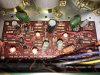
Thank you for all of the help so far. I have completely went through the P700 board and feel a little better about what is actually bad and what is not.

Most of the resistors were easy to test in the board. The readings that were way off I ended up removing one leg to test. I found another bad Transistor at H706, So I plan to replace the corresponding H708 along with it.

H706 - 2SC371Y : KSC945CGBU Fairchild Semiconductor
H708 - 2SA562Y : KSA733CGBU Fairchild Semiconductor

This is very close to the DIOD was bad at H716

H716 - 1N60 I saw someone else sub with these: BAT41 STMicroelectronics That okay?

When I took the P700 board out of the 1060, I had to cut the RCA cables that went to the board. Do you have any recommended wire to replace these? I think I can still use them, this is just for a backup plan if they're too short.

All of the Caps are out and I'm hoping to order most of the parts within the next couple of days.

I had a quick question on thermal compound. I haven't been able to find any recommended compounds or brands, just not to use Arctic Silver. Does anyone have any recommendations on what brand/ compounds to use?

Lastly, I used a woof chisel to clean up the old glue on the board (Worked great, although I killed a couple of resistors and one ceramic cap). There was some burnt marks on the board that I was able to scrape away. Do I need to do anything for the board with this? If so, what type and brand of epoxy is used as best practice?

Thank you again!!
 

Attachments

  • IMG_0344.jpg
    IMG_0344.jpg
    103.1 KB · Views: 34
I have heard of using BAT41 parts for 1N60 Ge diodes, but have never tried them.

If are talking about the shielded wires from the main in jacks to the amp module, any small, well shielded audio cable should work. If you cut the old one close to the connection point, you can probably just carefully prepare the ends and reconnect them the way they were.

I use Dow 340 thermal compound, although there are other brands such as Wakefield and Aavid.

I can't really tell from your picture, but if the burned marks are superficial, you probably don't need to do anything more than you have done. If the burned area goes all the way through the circuit board so that it forms a 'carbon path' between circuit traces, then you should grind it out and replace it with epoxy. I use clear, two part quick set epoxy and usually add some dust from ground up circuit board material.

Tom
 
I'm pretty sure I got lucky and it didn't go through the board.

This is a better shot.
 

Attachments

  • IMG_0341.jpg
    IMG_0341.jpg
    109.5 KB · Views: 62
if you need a germanium diode i may have a suitable one here ... depends on whether it needs to be germanium and where you are .... think they are mainly 0A something ...
 
So I'm almost finished with the power amp board. So much for Excel and the COUNT function... I didn't order enough of a few CAPS... So I'm waiting for those to come in to put the finishing touches on.

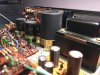
I am starting to move on to the Pre-Amp board for it's re-cap/checkup. I have been doing a lot of browsing to make sure C414,C415, C410, C411 are wired correctly. Looking at the board, they're a bit odd; anyways it appears that they're correct. While browsing through I stumbled across a question on the Output Transistors:

- KutzlerTrans had advised not to replace things it they're okay. Another member advised to replace all Output Transistors as best practice, is that true?
- CAPS C414, C415 don't show which side is positive vs negative. Does anyone know what the case is with these? I want to avoid that terrible sound of a CAP going off if possible...

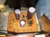
I started on the power supply, but needed to order another 100µF 50v CAP (Actually two, one for the Phono board).

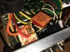
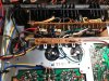
While I was browsing I ran into some posts about popping from the power switch. That made me think of what I saw with the bottom of the case removed. It looks like an oil film CAP with one leg soldered onto the powers switch. Is this normal? Or should both legs be soldered onto the switch? If it's the latter, what contact should it be connected to?

Lastly, does anyone have any suggestions on where to find a lamp lens for the front cover?I have looked all over and haven't had much luck. I'm not opposed to fabricating something together.

Thanks everyone for all the help. This has been truly enjoyable. Just sucks when you don't order enough CAPS.
 

Attachments

  • IMG_0380.jpg
    IMG_0380.jpg
    112.6 KB · Views: 58
  • IMG_0386.jpg
    IMG_0386.jpg
    127 KB · Views: 58
  • IMG_0384.jpg
    IMG_0384.jpg
    85.2 KB · Views: 56
  • IMG_0391.jpg
    IMG_0391.jpg
    97.5 KB · Views: 59
C414/C415 are bi-polar caps and do not have a +/-. You can put a bi-polar in place of a polar cap, but you must use a bi-polar to replace these. Looks good so far! Rich
 
That cap on the power switch is actually a cap + resistor that is on many Marantz models (as well as others). My understanding is that it is to smooth out current flow on startup and prevent a loud pop as well as protect downline components. I'm not sure why it isn't connected on one end, but it would normally be connected between those two terminals in the photo. Nice looking work. Well done! :thumbsup:
 
Last edited:
@Steven Tate Do you know what Wattage the resistor would need to be? I'm not able to find an integrated thin film cap and resistor like this one that's in here.

Anyone have anything on the questions listed above?
 
Here is a discussion about a similar part and a couple of options with part numbers.


http://audiokarma.org/forums/index....40b-need-help-with-a-replacement-part.586941/

As for replacing output transistors, it seems most of the recommendations I have seen from the experts is remove them, clean them and their mica insulators and replace with fresh thermal compound unless they test bad. Inspect the mica insulators for cracks and replace if necessary.
Steve
 
Last edited:
Hi Everyone;

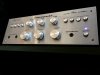
Just giving an update on this. The 1060 lives again! It sounds amazing!!

I originally bought this from a Vintage store in Waterville Maine (Modern Underground) to give to my father for Christmas. He had bought a Marantz 3200, 140, and a FM receiver (can't remember the model number) when he was in the Air Force. Lost it in the divorce which, I knew was pretty tough for him. I ended up saving the 3 from going to Goodwill by my mother. I've had the set for about 6 years at this point. I've loved having them, and I know my father was happy that I was able to rescue them.

My hope was to get this and do some small repairs to get it in working order. As it turns out, this was a much bigger job than I had envisioned. After hearing this thing for the first time I quickly fell in love with it. The 3200 isn't any slouch by any means... But this thing really sounds like it is on a different level.

At this point i was on the lookout for another 1060 to fix up and give him at Christmas (It sounds that good...). I was unable to find one in the price range I was looking for. So I settled for a 1060B (I know they're on completely different levels).

Anyways, he was over the house the other day to listen to the 1060. We started looking at his old two pair and he got a little emotional over them. So I've decided to recap the 3200 for Christmas, and work on the 140 shortly after (Sounds like a cap is filling up on the initial power up). Once I have that one done, I'll be giving him his pair back which will probably outlive both of us at this point.

I wanted to sincerely thank everyone for their help with information. Not just with this particular post, but every post I referenced on the site. I would have been hopelessly outmatched against these things without the guidance.

Oh, and did I mention the 1060 sounds truly special?!
 

Attachments

  • IMG_0459.jpg
    IMG_0459.jpg
    109.7 KB · Views: 62
  • IMG_0460.jpg
    IMG_0460.jpg
    88.2 KB · Views: 59
  • IMG_0467.jpg
    IMG_0467.jpg
    135.6 KB · Views: 60
  • IMG_0471.jpg
    IMG_0471.jpg
    80 KB · Views: 57
  • IMG_0475.jpg
    IMG_0475.jpg
    145.1 KB · Views: 62
  • IMG_0486.jpg
    IMG_0486.jpg
    42.9 KB · Views: 57
Back
Top Bottom