• The move to the new server is done. There are some software and database maintenance updates in process. This has us passing the hat around to help out. We appreciate any donations. Seriously, even a dollar helps. The payment page may be found here - https://www.audiokarma.org/support.html

Marantz 1060 right channel distortion

Elwood

New Member
Hi all-

Trying diagnose my 1060 issue.

Marantz Preamp is ok, ran preamp out from NAD preamp and still had a distorted sound on right.

It only occurs after powering up cold. Distorted sounds goes away after some time( 30 second to sometimes 5 minutes) then sound comes in clean. Once sound comes in clean it stays clean. Have played for hours. Replaced capacitors on amp board , no change. Suspect transistor , any thought? Which one to check for right side? Thanks all!
 
Register to hide this ad
+1

You can also try lightly tapping on each one with the handle end of a small screwdriver.
I have found a few offenders that way.

Bob
 
I have seen many, many bad electrolytic capacitors on 1060 (and 2230) power amps. Either a capacitor outright fails, or a 'leg' corrodes off.

Tom
 
The small signal transistors are pretty easy to replace. If the freeze spray doesn’t do it you could just shotgun the board.
 
I have seen many, many bad electrolytic capacitors on 1060 (and 2230) power amps. Either a capacitor outright fails, or a 'leg' corrodes off.

Tom
I replaced all the caps except the coupling and big filter power cap. Could a coupling cap cause this? I have some new caps but couldn’t get the exact values so was hesitant in putting them in... have two 4700uf 63v for the 3000uf 55v and one 10000 80v for the 4700 80v. Some say better to go larger here, but gut says keep original spec?? All other I kept the same.

Channel is staying distorted now...thinking I could pull output transistors to test....I guess I could swap left to right to test as well? What order are the 4 on the heat sink as far as left and right channels?
 
I replaced all the caps except the coupling and big filter power cap. Could a coupling cap cause this? I have some new caps but couldn’t get the exact values so was hesitant in putting them in... have two 4700uf 63v for the 3000uf 55v and one 10000 80v for the 4700 80v. Some say better to go larger here, but gut says keep original spec?? All other I kept the same.

Channel is staying distorted now...thinking I could pull output transistors to test....I guess I could swap left to right to test as well? What order are the 4 on the heat sink as far as left and right channels?
Checked output transistors with mm, no short or open. They read .593, .589, .628, ..644 from base and emitter. Did notice a missing little sheath on a leg of one of the transistors though
 
Check all the wires soldered to the pins of the main board did any break when you were working on that board? My guess is a bad transistor once the main amp board. Do you get distortion on all inputs? Or just phono? Some units from this model have 2sc458 transistors and should be replaced with ksc1845
 
Check all the wires soldered to the pins of the main board did any break when you were working on that board? My guess is a bad transistor once the main amp board. Do you get distortion on all inputs? Or just phono? Some units from this model have 2sc458 transistors and should be replaced with ksc1845
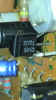
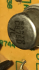
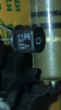
I haven’t checked phono, but the Tuner or aux, but also ran different preamp (Nad) in to main in and had same issue. Here are trans on that board. Checked pins, but had issue before my work as well.
 

Attachments

  • 496C3B21-E305-4216-A890-8289E48B8FCA.png
    496C3B21-E305-4216-A890-8289E48B8FCA.png
    303.4 KB · Views: 21
  • BFEA6CF2-80BF-48A7-B2CA-DF65A6BFE93D.png
    BFEA6CF2-80BF-48A7-B2CA-DF65A6BFE93D.png
    241.5 KB · Views: 16
  • FD6D7E9C-2D32-44D2-B49C-38738FDFD3D9.png
    FD6D7E9C-2D32-44D2-B49C-38738FDFD3D9.png
    225.8 KB · Views: 17
  • 9BC9BB42-F90F-45FC-9EA5-906EEE74EB62.png
    9BC9BB42-F90F-45FC-9EA5-906EEE74EB62.png
    284.2 KB · Views: 16
  • B166C925-374F-44CF-80DE-E6CCB5D461DA.png
    B166C925-374F-44CF-80DE-E6CCB5D461DA.png
    274.5 KB · Views: 16
While I doubt the the output coupling capacitors are the problem, I usually increase the value of them to 4700µF for better low end response, so the 4700µF/63 V will be fine as long as they fit the clamps and are not too tall to get the top on.
If you can carefully make a few DC voltage measurements in the defective amp when it's acting up, (volume fully CCW or pre-main jumpers pulled) it could be helpful.
Odd numbered components are the Right channel, even are LEFT, if I can believe the schematic.
You have the good channel to compare them too.
The J numbers on the bottom edge of the board would be a good place to start.
Meter set to DC volts, black meter lead to the chassis, measure with the red. Power will have to be turned on to make the measurement, so be careful! Wear rubber soled shoes and work with one hand in your pocket.

Let us know what you find.

Tom
 
Check the transistors on the preamp board if you are saying the fault is occurring both with the preamp and main amp
 
While I doubt the the output coupling capacitors are the problem, I usually increase the value of them to 4700µF for better low end response, so the 4700µF/63 V will be fine as long as they fit the clamps and are not too tall to get the top on.
If you can carefully make a few DC voltage measurements in the defective amp when it's acting up, (volume fully CCW or pre-main jumpers pulled) it could be helpful.
Odd numbered components are the Right channel, even are LEFT, if I can believe the schematic.
You have the good channel to compare them too.
The J numbers on the bottom edge of the board would be a good place to start.
Meter set to DC volts, black meter lead to the chassis, measure with the red. Power will have to be turned on to make the measurement, so be careful! Wear rubber soled shoes and work with one hand in your pocket.

Let us know what you find.

Tom
Thanks Tom- here is what I got for readings

J710 71.7v
714 37.7
712 38.2
720 0
716 37.2
718 37.2
722 0.5
724 0

709 71.3
713 36.3
711 36.3
719 0
715 36.6
717 36.7
721 0
723 0
 
Expect pin 721 to be about 0.6Vdc, means output H002 is not biased/turned on

EDIT: Double check this measurement, if still 0V then check H711 b/c/e voltages
to ground/chassis
 
Thanks Tom- here is what I got for readings

J710 71.7v
714 37.7
712 38.2
720 0
716 37.2
718 37.2
722 0.5
724 0

709 71.3
713 36.3
711 36.3
719 0
715 36.6
717 36.7
721 0
723 0
Channel staying distorted now all the time
Expect pin 721 to be about 0.6Vdc, means output H002 is not biased/turned on

EDIT: Double check this measurement, if still 0V then check H711 b/c/e voltages
to ground/chassis
yes, double checked 721 0 v. A little tight to test h711 in circuit or is there an easier way? Or should I pull that transistor to test it for short/open situation? Thank you!
 
A little tight to test h711 in circuit or is there an easier way?
Please don't attempt to probe transistor legs, instead probe connected parts, use minigabbers or similiar if needed.

H711e probe R743. You can probably skip this since it will be close to J711 +36Vdc
H711c, omit, already done, J721 0Vdc
H711b probe at J705

While you are there, measure at J707 also, maybe problems with diode pack H005.
 
Please don't attempt to probe transistor legs, instead probe connected parts, use minigabbers or similiar if needed.

H711e probe R743. You can probably skip this since it will be close to J711 +36Vdc
H711c, omit, already done, J721 0Vdc
H711b probe at J705

While you are there, measure at J707 also, maybe problems with diode pack H005.
J705 37.1
J707 37.4
 
Back
Top Bottom