• The move to the new server is done. There are some software and database maintenance updates in process. This has us passing the hat around to help out. We appreciate any donations. Seriously, even a dollar helps. The payment page may be found here - https://www.audiokarma.org/support.html

Marantz 115b P150 AM board is missing capacitor C159 maybe ??

Beamer302

Active Member
I am working on a Marantz 115b and the AM board P150 has a capacitor missing...I think . It is C159 a 20pF ceramic . It is listed in the parts list,component layout and is also on the schematic . On my board it shows evidence that it has been clipped off . The leads are still there . I know that board YD2890001-0 is used on other models . The board I have might be not original to this Marantz 115b tuner. My question... Is C159 (20pF) used on a 115b AM board ? Also C156 (5pF) shows up on the component layout and in the schematic as well . It looks like it was never on this board. This is why I want to know what is on an actual 115b AM board . Thanks . .
 
Last edited:
Register to hide this ad
Manufacturers often made mods as needed that do not get documented properly. If the main connections on that board look original I wouldn’t worry about it. Does your AM work? If yes, move on.
 
The board looks like it might have come from another Marantz just not a 115b . C159 looks like it was cut from its location on the board. The leads are still there. The wire connections to the board all have solder joints and are not wire wound .The AM works sort of . It is inconsistent in sensitivity when tuned from 540 to 1600 . around 1100 to 1400 it oscillates and whistles .The signal meter moves a little bit on some stations and pegs all the way to the right on others . Just would like to know it C159 is used on a 115b AM board .
 
Well I put a 20pF capacitor in the the C159 location and it killed the RF signal . Don't know if the board has other issues or not . I will keep checking things out as the AM is not right .
 
I have seen poor or no AM reception caused by a broken wire or a bad AM loop stick antenna assembly.
There are windings inside the black antenna assembly that are crucial for AM reception.

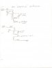
AFAIK there are two types depending on the model, 4 wire and five wire. While not a definitive test, if you disconnect the wires, the windings can be checked for continuity with an Ohm Meter.

Please forgive my poor drawing skills.

Tom

AM Loop stick.jpg
 
I will check the loop antenna . I was wondering how it was wired inside . Thanks for fine the schematic .
 
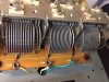
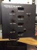
Well I got this unit working just fine now . On the P100 board I have , the wires to J109 and J107 were reversed . The antenna wire (yellow) needs to go to the J107 . (Farthest from the tuning drum) The J109 green wire (closest to the drum) needs to go to the connection pin at J155 (P150 board) . On the component layout in the service manual in Fig.7 of that page. It reads J107 , J108 ,J109. from left to right. On the actual board I have it reads J109, J108, J107 when reading them from left to right . So the board is labeled Wrong . So on the board I have I hooked up the wires to match the schematic & the component layout drawing . What got me thinking on this was that the black metal cover is labeled with the AM ant. adjustment on the end away from the tuning drum.The AM RF adjustment is near the drum. I hope this helps someone else too . I still don't know if C159 is used or not . AM is working fine right now after alignment . Here are some pictures . IMG_3759.jpg IMG_3760.JPG
 
Last edited:
Back
Top Bottom