• The move to the new server is done. There are some software and database maintenance updates in process. This has us passing the hat around to help out. We appreciate any donations. Seriously, even a dollar helps. The payment page may be found here - https://www.audiokarma.org/support.html

Marantz 1200 from HELL!!

skibjr

Super Member
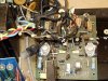
Well, at least some moron "tech" put it through hell, anyway. I've seen quite a few hatchet jobs over the past several years, but this ranks right up there as one of the worst.

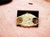
Picked this up off of the auction site about three years ago suspecting that it might have been tinkered with, but she had a pretty face so I thought I'd take a chance. Little did I know what I was getting into. I popped the top and took, one look, :yikes: then quickly covered it back up. Suffice it to say that she's been shelved ever since.

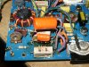
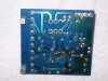
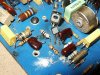
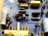
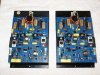
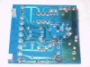
Finally pulled her out a few weeks ago and have been attempting to undo the carnage. I've included a few shots below. First off, there were two completely different driver boards - the left board was an earlier design (using the germanium bias diode) on blue phenolic; the right board, a later design with upright bias and offset pots, on green phenolic. Nice. Gotta love the impromptu RC network in the last shot... :no:
 

Attachments

  • 1200.JPG
    1200.JPG
    98 KB · Views: 360
  • Amp_Bd_L.JPG
    Amp_Bd_L.JPG
    120.9 KB · Views: 344
  • Amp_Bd_R.JPG
    Amp_Bd_R.JPG
    108.2 KB · Views: 315
  • L_Amp_Detail-1.JPG
    L_Amp_Detail-1.JPG
    118.3 KB · Views: 349
Register to hide this ad
The more thermal compound, the better the tech, right?

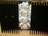
Thermal compound everywhere - it took me over an hour just to "de-grease" the amp! I'm thinking this particular tech must've had a day job frosting cakes for Betty Crocker...

I was particularly impressed with the mounting technique used for the TO-66's - the nylon spacers he used lifted the transistors about 1/16" off of the heat sinks. The solution? Fill the gaps with thermal compound! :bash:

Not surprisingly, the TO-66's were all dead. Most of the outputs were toast as well.
 

Attachments

  • L_Amp_Detail-5.JPG
    L_Amp_Detail-5.JPG
    85.6 KB · Views: 232
  • L_Amp_Detail-4.JPG
    L_Amp_Detail-4.JPG
    116.7 KB · Views: 230
  • L_Amp_Detail-7.JPG
    L_Amp_Detail-7.JPG
    71.2 KB · Views: 199
...and now for some innovative soldering techniques...

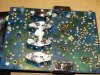
Nothing like soldering new transistors to the chopped off leads of the old ones. I mean, why waste the five whole minutes it might take to properly pull the driver board? Some nice work done on the circuit side of the relay board as well...

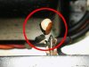
Finally, the last shot is a little tantalum cap that was connected between the shielded side of one of the "Amp In" connectors and ground - probably to block DC from the preamp section. Looks like it took a few volts, huh?

Well, that's it for the "before" pics. "After" pics to follow in a little while...
 

Attachments

  • Tantalum.jpg
    Tantalum.jpg
    43.5 KB · Views: 267
  • Relay_Bd.JPG
    Relay_Bd.JPG
    82.5 KB · Views: 195
  • L_Amp_Detail-3.JPG
    L_Amp_Detail-3.JPG
    114.5 KB · Views: 219
  • L_Amp_Detail-2.JPG
    L_Amp_Detail-2.JPG
    88.9 KB · Views: 218
Nothing like soldering new transistors to the chopped off leads of the old ones. I mean, why waste the five whole minutes it might take to properly pull the driver board?

I think that technique was a favorite of TV repair technicians, because the PCBs were a great deal more difficult to access in many TV older chassis. I used to see it pretty commonly in my shop, sometimes in jobs that were sub-contracted to us directly from TV service shops.
 
It's obvious to me this was done by someone who takes no pride in their work since those transistors' legs aren't even bent neatly. I could understand burnt insulation from an amateur job but this seems like he didn't care.
 
I'd agree that the person did not care, but I think they just didn't know. If you're doing it professionally, the last thing you'd gap a thermally mounted driver/output transistor. Even a small amount of knowledge would tell you, "That's coming back as a re-work".
 
The horror. The horror.

Jack the Ripper as audio repair person. Actually, Jack would likely do a better job.
 
I'm working on a tampered with Marantz 250 amplifier for a fellow AK member. The prior owner connected wires all over the amp...then powered up!
There are many pieces of gear out there that was tampered with then sold.
 
There are many pieces of gear out there that was tampered with then sold.

S'pose I shouldn't complain - if she had been properly serviced, I wouldn't have won this wonderful old amp for a song, nor would I have had the enviable pleasure of getting to know her so intimately! :D
 
Ouch Dave! You got your work cut out for ya there. I know you'll make that sucker shine like a diamond! :yes:
 
Progress so far...

Well, the key to this restoration was getting a hold of two matching amp boards, and to that end, I kept my eye on eBay for almost a year before a pair popped up in Canada. Unfortunately, they had already both already been plundered for parts, but I figured between these and my existing boards, I should be able to come up with a complete matching set. Moreover, these were the later "MKII" boards with the simplified bias circuitry and more easily accessible bias and offset pots. With time and a little help from Mouser, I was able cobble together a reasonably acceptable set. How well they'll work remains to be seen...

Rather than messing around trying to find suitable matching sets of TO-66 drivers, I went with the more standard On-Semi TO-22s (MJE15030/31). Members seem to have had pretty good luck using MJ21193/94s for output subs on these amps, so that's what I installed after cleaning the greased-up heat sinks.

I pulled all the boards, recapped everything, and scrubbed the gunk off of the chassis and all the wiring. Burnished the relay contacts and 'DeOxit-ized' all the switches and pots. (It ain't easy getting at the front panel controls in the 1200 - you pretty much have to pull almost every board first.) There wasn't much I could do with the hosed up traces on the relay board, but I was able to clean things up a little. Pics are below.

Hopefully this weekend I'll have some time to reattach the amp assemblies and run some juice through her. It's been a long road with this one - hopefully she'll be singin' again soon. Wish me luck! :)
 

Attachments

  • amp_bds.JPG
    amp_bds.JPG
    105 KB · Views: 229
  • heatsinks.JPG
    heatsinks.JPG
    77.7 KB · Views: 195
  • relay_bd.JPG
    relay_bd.JPG
    94 KB · Views: 187
  • stripped.JPG
    stripped.JPG
    122.5 KB · Views: 201
  • partial_assy.JPG
    partial_assy.JPG
    123.8 KB · Views: 217
Last edited:
Those first few pics are gruesome. I'm working on a SPEC 2 that I thought was pretty bad. Nothing compared to this 1200 mess.

You did a great job on those driver boards.
 
...Fill the gaps with thermal compound! :bash:...

Ok, as someone who does a lot of computer repair I know that filling the gaps with thermal grease is just going to cause it to cake in there, be a PITA to remove and is going to actually to overheat rather than cool. Personally if I had a gap I would've invested in some thermal pads to fill the gap rather than just the compound, since the thermal pads are designed to fill in gaps.
 
Ok, as someone who does a lot of computer repair I know that filling the gaps with thermal grease is just going to cause it to cake in there, be a PITA to remove and is going to actually to overheat rather than cool. Personally if I had a gap I would've invested in some thermal pads to fill the gap rather than just the compound, since the thermal pads are designed to fill in gaps.

But a gap of over 1/8 inch is going to cause much more thermal resistance due to the thickness of the material - only metal and appropriate thermal grease would be useful. But the real answer would have been to get the proper insulating bushing that would allow flush case mounting while insulating the screws. If the bushing was too long, simple to cut it down. Someone wasn't making very good decisions.

Skibjr, btw, on the original board, were the driver transistors Motorla HEP marked? Those were Motorola's hobbyist/experimenter line, which in some respect evolved into a general replacement line similar to Sylvania/Philips ECG semiconductors. Speaks to the level of "professionalism" used in this units previous work. Pretty sad looking to say the least. Glad you're on it for restoration, looking forward to your progress.
 
Seems like Marantz gear somehow attracts morons like this... my CD-330 tape portable looks a lot like your amp! Plenty of broken and missing screws, soldering iron marks ON THE OUTSIDE of the case, original wires randomly replaced with much thicker ones (I suspect he plundered an extension cord for some of those connections, like one wire to the internal speaker). Oh, and the glass fuse with a single strand of copper wire soldered(!) across it was a nice touch too... Their soldering skills look to have been up to par too... I mean I'm bad at soldering, especially due to lack of practice, but it still looks a lot less messy than what that guy did!
 
Update...

So, after completing assembly of the amp modules, I wired everything back up and fired her up on the DBT. The bulb lit up then dimmed down just like it should........ but no relay click. :dammit:
Measured offset on the right channel - good - just a few millivolts. Measured the right channel, and discovered a nice fat negative 49V - the full negative rail. :yikes:
Pulled everything apart, checked the pre-drivers (everything else was new), but found no shorted junctions. Ran a few comparative passive resistance measurements between the right and left channel boards, and found no differences whatsoever. It's always lots of fun running down the cause of DC voltage on the signal line, because there are so many ways it can get in, and once it's there, it's everywhere. I finally figured out that the negative side predriver was breaking down under load, even though it tested fine out of circuit. Okay fine - replace the predriver pair, hook everything back up and bring it back up on the DBT. Now, no DC on either channel......but STILL no click! :wtf:

C'mon, already!!

Pull it all apart AGAIN, pull the filter caps, 'cause they pretty much block all access to the relay board, unscrew the relay board and start checking parts. Turns out CR707, a 19V 5 Watt zener diode regulating the supply voltage to the relay coil was dead shorted to ground. :no: Guess that would explain no relay click, huh? Well, all the zeners I have in stock run one watt or less, but I have an old Marantz 250 parts unit that shares many of the same boards with this 1200, so I thought I'd pull the 5-watt zener off the 250's relay board to see if that would finally get me my click.

Well, guess what? Apparently, the 250's relay circuit doesn't use a zener! :dunno: Figures. So, now I'm waiting for parts from Mouser yet again. Hopefully next weekend, I'll be able to finish this beast once and for all. I've never had the opportunity to audition a Marantz 1200, and I'm really looking forward to it... :yes:
 
Great job on the amp so far. You do really good work, the difference is night and day.:thmbsp:


Ok, as someone who does a lot of computer repair I know that filling the gaps with thermal grease is just going to cause it to cake in there, be a PITA to remove and is going to actually to overheat rather than cool. Personally if I had a gap I would've invested in some thermal pads to fill the gap rather than just the compound, since the thermal pads are designed to fill in gaps.

There should never be any gaps between the semiconductor case and the heat sink, so thermal pads.:no: Fix the problem, don't hide it.
For best thermal transfer there should never be anything between the semiconductor case and the heat sink. The only time anything is placed between the case and the heat sink is if the case needs to be electrically isolated from the heat sink. Even then, the insulator should be as thin as possible. Thermal compound is only there to fill-in any microscopic voids and nothing else. The most efficient heat transfer would be to make sure the mounting surface of the heat sink and the semiconductor case are perfectly flat and polished then use a minimal amount of thermal compound.
 
Back
Top Bottom