• The move to the new server is done. There are some software and database maintenance updates in process. This has us passing the hat around to help out. We appreciate any donations. Seriously, even a dollar helps. The payment page may be found here - https://www.audiokarma.org/support.html

Marantz 1200b no audio

That may be part of your problem, it might be limiting the current too much for proper operation. If you don't see a sustained bright light after power on, you can pull the DBT out of the way.

I would hook both the 250's back up, and let it have full current. But use every precaution, such as a power/surge strip with a master off switch in between the wall and amp.
 
That may be part of your problem, it might be limiting the current too much for proper operation. If you don't see a sustained bright light after power on, you can pull the DBT out of the way.

I would hook both the 250's back up, and let it have full current. But use every precaution, such as a power/surge strip with a master off switch in between the wall and amp.

Ok i removed the DBT, unit stays on, still no relay with 250's hooked up, outputs still out of circuit. With both 250's removed relay closes, If I connect one or the other, no relay.

There must be something that is common to both 250's that is causing this?
 
That is a strange result.

Do you have any pics of your Power Supply and Relay board?

I'm thinking the Relay board is having problems, it's common to both 250's.
 
That is a strange result.

Do you have any pics of your Power Supply and Relay board?

I'm thinking the Relay board is having problems, it's common to both 250's.
I will try to get a pic tomorrow, I replaced the relay with one that I modded, I also replaced the caps and resistors on the board. Wish I used axial, but its not to bad looking.
 
Do you still have the stock relay, was it pitted or damaged beyond repair?

Did yours look like this one?
uyIXeCx.jpg
 
That is a nice one. I also built the Omron mod, and during the troubleshooting of my 1200, I used the stock one and never put the Omron back in.

They look like they're built to last forever, might see if putting the stock one back in makes any difference, or leads to another discovery in the process.

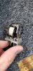
Easy to pull apart and clean, built like the points in a car distributor - they don't make them like this anymore:
NGNF3W0.jpg
 
That is a nice one. I also built the Omron mod, and during the troubleshooting of my 1200, I used the stock one and never put the Omron back in.

They look like they're built to last forever, might see if putting the stock one back in makes any difference, or leads to another discovery in the process.

Easy to pull apart and clean, built like the points in a car distributor - they don't make them like this anymore:
NGNF3W0.jpg
I will try this and see if it make a difference. thank you for all your suggestions, I am learning a lot about this unit.
 
when I did mine, i:
wired up power supply to one channel
tested every transistor starting at the outputs and working back
dbt (150w bulb)
measured every base,collector,emitter and compared with schematic
fixed/replaced most transistors, many blown resistors, ...

set bias/dc offset
repeat with other side

I also had to replace the transistors on the relay board to get the protection relay delay working.
finally recap as needed

post results if you are not sure.

I thought these amps were one of the most difficult to repair but with some logic, patience, and a bit of luck, you should be able to fix it.
 
when I did mine, i:
wired up power supply to one channel
tested every transistor starting at the outputs and working back
dbt (150w bulb)
measured every base,collector,emitter and compared with schematic
fixed/replaced most transistors, many blown resistors, ...

set bias/dc offset
repeat with other side

I also had to replace the transistors on the relay board to get the protection relay delay working.
finally recap as needed

post results if you are not sure.

I thought these amps were one of the most difficult to repair but with some logic, patience, and a bit of luck, you should be able to fix it.
Thank you, ill get a larger bulb for my DBT and try this. Do you recommend any particular transistors if i need to replace those on the power/relay boards?
 
Thank you, ill get a larger bulb for my DBT and try this. Do you recommend any particular transistors if i need to replace those on the power/relay boards?

there are a few threads on transistor replacements. 250, 240, 250M, 1200 1200b have similar power amp boards and protection boards. I'll see what I used but let's get it working before we need to replace the protection transistors. My symptoms was the transistors were leaky and turned on the relay on power up. not after a few seconds.

once you get the relay to close, we can fine tune your integrated.

I think there are two yellow wires to the protection board. one for each channel. these need to be less than .7v (or something) to get the relay to trigger. once you feel the amp boards are working, we can focus on the other boards.
 
pins 5, 6 on the protection board. on my 240 and 250, these are yellow. I'm at work so I can't look at my 1200. you can just backtrack from there to see where the pins are on the amp boards.

looking at the factory 1200 service manual, they might be pin 19 on the amp board. hopefully your model 1200b is similar.
 
pins 5, 6 on the protection board. on my 240 and 250, these are yellow. I'm at work so I can't look at my 1200. you can just backtrack from there to see where the pins are on the amp boards.

looking at the factory 1200 service manual, they might be pin 19 on the amp board. hopefully your model 1200b is similar.
Its very similar, pin 19 on the amp boards are around 50v, R546 is giving me no measurement it looks like is should be a 1ohm 2w resistor, ill try taking it out of circuit to test. the transistors Q516 and Q517 are not shorted atleast.
 
I had a blown resistor that put 50v on the protection line. Once you narrow down what channel is bad, check the resistors when you test the transistors.
 
Which resistor was it if I may ask?
i might have been R515 but it might have been R527. I really hate to guess.

I don't have my notes here (on a different computer that I don't have access to right now).

I measured EBC voltages for all the transistors and compared them to the schematic.
 
i might have been R515 but it might have been R527. I really hate to guess.

I don't have my notes here (on a different computer that I don't have access to right now).

I measured EBC voltages for all the transistors and compared them to the schematic.
I found no bad resistors, however it looks like Q510 is shorted, Q511 checks ok. I have 50V on Q521 (should be 0v or 0.7v) both channels. Removed Q510/Q511 no change to voltages. Any Ideas?
 
I was able to get the relay to come on with Q510 and Q511 removed and after replacing R516. however I still have 45v give or take on Q521 (should be 0V). Any Ideas?

Q510 and Q511 are not reading short in or out of circuit.
 
Back
Top Bottom