• The move to the new server is done. There are some software and database maintenance updates in process. This has us passing the hat around to help out. We appreciate any donations. Seriously, even a dollar helps. The payment page may be found here - https://www.audiokarma.org/support.html

Marantz 140 Power Amp – Intermittent Fluctuating Right Channel

Hi Tony,
I hope this gets to you in reasonable time. I have been busy here and now at midnight I have a few minutes to check postings. On your amp the components in question appear to be in the feedback circuit which feeds back some of the output audio back to the input and the desired feedback phase is 180 degrees to suppress oscillations. Putting your finger near a transistor or on it and you introduce stray capacitance to those sensitive parts which accounts for the change in what you are hearing at the speaker. Looking at this circuit and the component values unless I missed something feeding audio from another amp into the output of this one does not seem possible to affect the components you are looking at. You can replace those transistors as a sort of shotgun fix. If that fails then you will need an oscilloscope to trace the signals in search of the offending oscillation. Even though you are hearing a low frequency oscillation at the speaker bear in mind the scope may show an oscillation at 100Khz or so.
To summarize my thoughts, the problem could be before the transistors in question. It is hard to say what the effect would be in that circuit if one of the transistors were intermittent but typically they just quit and would not exhibit the low frequency oscillation you describe. An oscilloscope sure would be handy to visualize the signal path! Do you have a scope or can you acquire one?

-Duane

Oh yes, you have that curve tracer to test the transistors. If the curves look good over a range of temperature and compare they are good.
 
Last edited:
So, my thoughts are now to replace H708 (2SA733 P.Q), these are hard to come by, does anyone have a recommended replacement?
If I did use a replacement would it be worthwhile to replace H705, H707 & H706?

Hi All,

I have finally received the new transistors to replace the four mentioned above, they are Fairchild KSA733CYTA & KSC945CYBU. I have a 100 of each type. I have a Peak DCA75 to test the HFE of the transistors.

I have removed the four transistors from the right channel amp board and tested them, the results show the following HFE

H705 – NPN - 138
H706 – PNP - 210
H707 – NPN - 143
H708 – PNP - 215

As I am very new to the game of matching transistors, I would like to seek experienced AK members comments on the following.

With the new transistors, do I match the HFE to have all four the same, say 175 HFE or do I match the HFE as close as possible to the original HFE, say 140 & 212 HFE?

Or do I replace with higher HFE values for all, but match in pairs?

Tony
 
There is no matching required for these bjts H705-708. These are part of the current limiter circuit. They are only enabled(turned-on) if/when you have a over-load/over-current/short-ckt condition that would potentially damage other devices like the o/p bjt's,H001/002. The current is sensed by R740(0.2ohm). So a voltage drop of around 0.6V turns on either or both H705-H706, which then turns on H707-708, which then shorts the drive from H711/H712. They are not required to make the amp work.
The only matching in this circuit is the input pair, H701-702. This keeps the DC offset within reason or range so that you can adjust to 0V using R741(2K pot) and does reduce some input section THD. You can match the o/p's bjt pair's as well, for hfe, H001/002, but this is not absolutely necessary.
But to answer your question, match the hfe for the same gain.
As for hfe range, the parts list tells you what gain range is acceptable. So for H705-7, the NEC spec for 2SC945(Q,R) is
Q= hfe=135-270
R= hfe=90-180
 

Attachments

Hi All,

Thank you rcs16, you have provided me with a great insight into the workings of the amplifier board. I now wonder if these transistors are just a symptom of the problem and actually doing their job as the amp board goes into this fault condition (intermittent fluctuating)?

Tony
 
Change them now that you have new ones. Lets hope they are the culprits, and hope it is penny parts to fix your unit, which would be really nice.
I would also advise, to take out the power transistors, clean them up, put new thermal compound, mica washers and even spray a little contact cleaner(de-oxit) on the transistor sockets, insert the transistors back and forth a few times, to remove the old tarnish. Do not over torque the screws. Measure the EBC to see that there is no shorts to the heatsink which should be ground potential.

God luck
Rick
 
Hi All,

Thanks for your comments Rick, I will certainly replace these transistors, and as you say may fix the problem. I will let you know the outcome.

Regarding the output transistors, I will replace the thermal TO-3 heat pad and apply thermal paste, are you saying that the mica board on the other side of the heat sink that has the wiring terminals on it should be replaced? And are these available?

Tony
 
Hi All,

I have replaced the transistors H708, H705, H707 & H706. These were replaced with Fairchild KSC945CY & KSA733CY from Mouser, with the pairs HFE matched. The amp has now been running for about 50 hours and all good so far, let’s keep our fingers crossed.

I have only changed the transistors in the right channel, the left remain original.

Tony
 
Marantz 140 comment

I just spent time to re-cap and rebuild a Marantz 140. Doing a proof I noted erratic IM distortion. Traces to the output protection relay. Contact bounce and oxidation were source of erratic IM. Could also be an intermittent output issue for others?? Could not get plastic relay cover off with out destruction. Figure speaker current would 'seal' the contacts. In its prior life unit was left on 24x7. i.e. relay never get exercised to 'wipe contacts'. I never noticed it does not have a power switch until the rebuild. Specs were solid. Dist was always under 0.1%. Response was flat 10 Hz to 75 KHz, Noise ref to 9 v out was -72 dB. Just a solid hi power op-amp! Only thing I failed to get was the idle current tune up. Appears outputs were replaced at some time in the past with less than identical units. Does not appear to be an issue. Sounds sweet into a pair of JBJ studio monitors. Ran cool in front channel movie sound mode.
 
Dear all!

I recently changed the dual caps to two mundorf 15 000uF 63v to try to resolve my random "hum" issue but no chance... I still have the issue. The unit as been checked last March 2016 (all the caps has been changed)

The issue : randomly, the left chanel begins doing a low "hum" and it increase until it goes loud and the VU meter goes left and right (and my woofer goes in and out too). To resolve the issue (temporarily) I need to power off/power on the amp (I am using a Marantz 3600 as Pre Amp) or remove/insert the 1/8 jack from my Airplay. Also, I can temporarily resolve the issue when I hit the first plug of the "switched" outlets from my Marantz 3600.

I was sure it was a bad grounding in my housing but... no !

As I can read on this post, it's possible it could be a bad transistor or a cold solder joint.

Is someone had the same issue than me? I have some soldering skill.

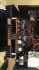
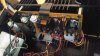
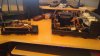
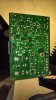
On one of the pictures, it is normal that two pins are solder together? (20170219_165618)

Thanks !

Guy
 

Attachments

  • 20170219_162320.jpg
    20170219_162320.jpg
    41.3 KB · Views: 49
  • 20170219_162342.jpg
    20170219_162342.jpg
    68.1 KB · Views: 46
  • 20170219_162542.jpg
    20170219_162542.jpg
    64.5 KB · Views: 46
  • 20170219_163239.jpg
    20170219_163239.jpg
    48 KB · Views: 43
  • 20170219_165618.jpg
    20170219_165618.jpg
    41 KB · Views: 45
Did you look at the differential input pair??
Its a known issue that they will oscillate as they age out.
They are the (2) to98 transistors with the shrink tubing holding them together for proper thermo tracking.
 
Did you look at the differential input pair??
Its a known issue that they will oscillate as they age out.
They are the (2) to98 transistors with the shrink tubing holding them together for proper thermo tracking.

Dear raidermc,

Thank you for you reply.

What is the differential input pair? Do I need to do some reading?

I can't see to98 transistors on my Marantz 140 manual.

It is on the P700 board?

Thanks !

Guy
 
Yes its on the 700 board. its H701 and H702..
If you change them make sure you closely match the gain of the transistors.
Typically when I get an amp or receiver with blasted outputs I automatically replace them, (cheap insurance).
 
Yes its on the 700 board. its H701 and H702..
If you change them make sure you closely match the gain of the transistors.
Typically when I get an amp or receiver with blasted outputs I automatically replace them, (cheap insurance).

Dear raidermc,

Thanks again for your reply.

I will check that for sure. I will make sure to have matched pairs.

I will let you know the outcome.

Thanks !

Guy
 
Yes its on the 700 board. its H701 and H702..
If you change them make sure you closely match the gain of the transistors.
Typically when I get an amp or receiver with blasted outputs I automatically replace them, (cheap insurance).

Dear raidermc,

Quick question for you.

What is the remplacement of the 2sc1327 ? I see on the net it's TO-92 2sc1327 as the original transistor.

Thanks !

Guy
 
Yes my mistake it is to 92 not to 98.
Senior moment as I get those two styles mixed up.
I use NTE 199 with good results.
OnSemi transistors is the preferred option on this forum but not sure what the cross reference is.
 
Last edited:
Yes my mistake it is to 92 not to 98.
Senior moment as I get those two styles mixed up.
I use NTE 199 with good results.
OnSemi transistors is the preferred option on this forum but not sure what the cross reference is.

Dear raidermc,

It seems the correct remplacement is the NTE199. I will buy some of these transistors to have matched pairs.

I can't see any of these transistor on Mouser or PartsConnexion. The website I found is Newark. I live in Canada so I need a Canadian supplier!

Quick question again there, what is the best reading to have on transistors to have matched pairs?

Thanks again!

Guy
 
http://www.nteinc.com/specs/100to199/pdf/nte199.pdf

If you can get to less then 5% of each other you should be golden.

Dear raidermc,

Alright, it's noted.

The only thing is... I don't know how to test it but I am sure it's using digital/analog voltimeter. I will learn on that!

Also, it is... voltage, resistance or amperage for the reading?

As I see on the PDF, I need to read each legs (Emitter and Collector) and must be close to the max value and 5% of each transistor to have a match. Am I correct?

Thanks!

Guy
 
Back
Top Bottom