• The move to the new server is done. There are some software and database maintenance updates in process. This has us passing the hat around to help out. We appreciate any donations. Seriously, even a dollar helps. The payment page may be found here - https://www.audiokarma.org/support.html

Marantz 170DC Offset, Help!

Nac458

Member
Hey all,

I've just recently completed a complete re-cap and restoration of a Marantz 170DC.

I received the unit in non-working condition. The entire right channel amplifier was disassembled and the output transistors had been removed as they were burned/shorted.

I went in and replaced components that appeared to be out of spec: all capacitors (including the main filter cap), any burned resistors/diodes in the right channel, the smaller output transistors on the 'mini' heatsinks on either amplifier board, plus all the fuse lamps in the VU meters up front.

Fast forward to being substantially complete.
I had to toggle with the soldering points behind the amplifier boards as the circuitry has seen better days and is a tad corroded. I fixed all cold solder joints and even did a bit of point to point soldering for the weaker areas.

Giving it a first listen and it sounds incredible! Really like nothing I've heard before.

About 10 - 15 minutes into my listening session, I noticed the left side of the amp (left channel) was significantly warmer than the right. I switched it off and proceeded to take measurements for DC offset. I used the R719 trimming resistor to adjust the offset, yet when I would get it right where I wanted +/- 0.5 mV the reading would gradually veer off (yes, the gain was turned all the way down). I ended up with somewhere around -500mV! I did some poking around today - testing continuity between some shoddy areas, and tried again. No difference, except the trimming resistor doesn't even seem to get close to the 0mV I was able to achieve before. It was reading somewhere in the 2V range!

Could it be a bad trimming resistor? Or a smaller transistor?
Is that a good place to start?
 
Register to hide this ad
Ive had this happen with several of the Marantz intgrated and power amps ive restored. Replacing the old carbon encrusted trimmers did the trick. You can use single or multi turn trim pots. Mouser is your freind here. Find a nice set of Bourns.
 
Ive had this happen with several of the Marantz intgrated and power amps ive restored. Replacing the old carbon encrusted trimmers did the trick. You can use single or multi turn trim pots. Mouser is your freind here. Find a nice set of Bourns.

Thanks Lavane!

I will get on to ordering new trimming resistors and see what I find.
 
Okay,

I've replaced the trim pots and it's a bit more stable.

However, I was listening to the amplifier today, keeping close watch of the DC on my multimeter - when all of the sudden I heard a loud pop in the left speaker and saw my meter was reading over-load.

It was doing this sporadically before I switched the trimming resistors. Whenever I would switch the speakers on, the pop would occur with some low hum electrical feedback on the left channel temporarily.

Do any of these symptoms sound familiar? Perhaps a shorted diode?
 
Possibly. One of the 140 power amps I have had a very similar problem. A pop and then very low distorted sound. It turned out to be a bad electrolytic cap on the amp board for that channel. Marantz loved to use that brown glue on caps and if it gets on the cap leads it corrodes the leads. The cap can look just fine untill you remove it and see the bottum.
 
Possibly. One of the 140 power amps I have had a very similar problem. A pop and then very low distorted sound. It turned out to be a bad electrolytic cap on the amp board for that channel. Marantz loved to use that brown glue on caps and if it gets on the cap leads it corrodes the leads. The cap can look just fine untill you remove it and see the bottum.

Gotcha

Think I've found the issue.

One of the 5.6kohm 1 watt resistors is testing rather weak. It's allowing 1.56 V through while it's counterpart tests around 0.6V. I'm going to replace both pairs along with a few other resistors that appear suspicious.

Will report back soon.

Thanks!
 
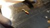
I've replaced all parts and saw this little guy break off at the pivot point.

20170130_161411_HDR.jpg

Despite my new components and brand new connection, the DC still jumps around.

I now suspect it is the potentiometer for the left channel. It is a bit more loose and free moving than its brother on the right channel. I've already cleaned them as much as possible.

Any idea where I can get replacement gain pots?

Thanks.
 
Gotcha

Think I've found the issue.

One of the 5.6kohm 1 watt resistors is testing rather weak. It's allowing 1.56 V through while it's counterpart tests around 0.6V. I'm going to replace both pairs along with a few other resistors that appear suspicious.

Will report back soon.

Thanks!
could you please tell us which resistor and method of testing ? . i dont understand your methodology here .
 
could you please tell us which resistor and method of testing ? . i dont understand your methodology here .

Perhaps I may have been measuring them incorrectly, as the symptoms are somewhat the same...

I was using the diode setting I believe, lol.

However I pulled them both and found one had drifted to 5.72kohms. See pic below:

20170112_223706.jpg

The solid 1 watt green/teal resistors were my concern and have been replaced. Yet the DC is still askew.

I'm thinking about finding replacements for the gain pots.

It's worthwhile to note that when I'm monitoring the left channel DC and toggle with the gain control (increase & decrease the knob) the DC jumps up to about 25-30mV with no load (starting from a flatline of ~0mV). When I repeat the process on the right side, there is no jumping of DC, even as I attenuate the gain control. This is after the amplifier has had significant time to warm up.
 
be more the pots but change resistors anyway if suspect .

Tested the variable resistors and they seem good. Even the left gain potentiometer tested well.

However, as I was monitoring DC simultaneously - I noticed the direct current is much lower with no load on the left channel. The right channel is stable with or without a load.

And before I'm off to bed - I was staring at the multimeters one last time today, watching the left channel figit from 5-15mV while the right stood planted around 1mV.

The interesting thing is when I powered the amp off, the DC on the left channel immediately went down to 0mV while the DC on the right channel shot up to 19mV. What might be the cause of this see-saw activity?
 
I noticed the left side of the amp (left channel) was significantly warmer than the right. I switched it off and proceeded to take measurements for DC offset.

Do you mean you meant to check the bias current (idle current)?
 
Last edited:
I have just had a look at the service manual and yes you are correct, this is a little odd, having no way to adjust bias, don't know if other Marantz's are like this or not? But uneven BIAS left/right would be your concern with uneven heatsink temp not the dc offset.
 
I have just had a look at the service manual and yes you are correct, this is a little odd, having no way to adjust bias, don't know if other Marantz's are like this or not? But uneven BIAS left/right would be your concern with uneven heatsink temp not the dc offset.

I'm swapping the rectifier for a new one currently. The rectifier was testing open in both directions - not good. Hopefully this will alleviate the symptoms and solve the mystery.
 
Here's what I found.

This amp is littered with weak leads and poor circuit tracing.

Found this resistor that easily snapped off the end. I suppose the lead was brittle.

20170201_172505.jpg

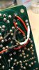
I replaced the 220ohm 1/4 piece - note the white shrink wrap.

20170201_172355_HDR.jpg

Much more stable now - yet I don't think the new rectifier made a huge difference. Turns out the old one wasn't bad at all.... Oh well.

This amp was in pretty rough shape when I got it, so the tracing had definitely seen better days (seemed like someone stored it outside or in an attic/basement/barn). I've done some point to point mods as you can see. Could corroded tracing on the board cause such symptoms?
 
Back
Top Bottom