


Nac458
Member
Hey guys,
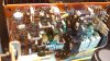
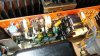
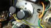
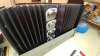
Just finished installing new capacitors and output transistors on a Marantz 170DC I have.
This has been my most significant project yet, so when I hooked it up to my current limiter and the bulb went dim - I was quite relieved.
*However, I did notice that the relay took a while to click in.
*I repeated the on/off process and the relay would vary in timing of clicking.
*No sound from the right channel either, only a loud hissing from the left channel (with the gain turned all the way down).
I proceeded to check the transistors on the relay board, and they are still good.
*Another curious thing is when I went to check the DC offset. My readings would start somewhere in the 1.50mV range then slowly travel backwards into the -. Any tips? Something I'm doing wrong?
Thanks!
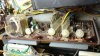
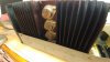
It's also worth noting that I had to replace a few burned resistors in the right amp board. Perhaps a few other components may have been effected from that mishap whenever it took place (I did replace the main transistors on the board). Added a before pic of the old transistors for fun.

Just finished installing new capacitors and output transistors on a Marantz 170DC I have.
This has been my most significant project yet, so when I hooked it up to my current limiter and the bulb went dim - I was quite relieved.
*However, I did notice that the relay took a while to click in.
*I repeated the on/off process and the relay would vary in timing of clicking.
*No sound from the right channel either, only a loud hissing from the left channel (with the gain turned all the way down).
I proceeded to check the transistors on the relay board, and they are still good.
*Another curious thing is when I went to check the DC offset. My readings would start somewhere in the 1.50mV range then slowly travel backwards into the -. Any tips? Something I'm doing wrong?
Thanks!
It's also worth noting that I had to replace a few burned resistors in the right amp board. Perhaps a few other components may have been effected from that mishap whenever it took place (I did replace the main transistors on the board). Added a before pic of the old transistors for fun.
