
Steven Tate
CEO Flat Forehead Soc.
How about the diodes?



Well. 4 diodes removed and measures are ok. 0.6V one way and OL on the other way.To test the diode, you need to remove one end from the circuit, then using the diode test function, measure through the diodes both ways (by swapping the test leads). One direction should measure about 0.6V drop and the other direction should read OL or something similar. If you test in circuit, the current may be finding an alternate path.
 Resistors R736 and R738 are 0.40 ohm. I think that it's ok even though should be 0.22 ohm. I'll continue testing all resistors on RH side circuit.
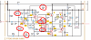
Wow. That’s a lot of variation from spec. Do these resistors look original? Normally, I would replace them with metal film resistors if they are more than 5% out of spec. But you have to be careful, because Marantz changed a lot of values after their schematics were published. Basically, if they look original, and are out of spec, I look at the color code on the resistor. If it is close to my measurement, I leave it, and hope it is the right thing to do. Are all of these measurements in-circuit? Again, if I measure in-circuit, and they test out of spec, I raise one leg and test again to verify. The interesting thing to me is that I’ve never found so many resistors that far out of spec. When I find a problem, it’s usually one or two resistors that measure open (Mohms). Also, with that many out of spec measurements, I would check my DMM against some new resistors to make sure it isn’t in a low battery state or something.
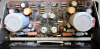
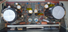
Which leg i have to raise? Anyone?If the color code matches the schematic, and they test more than 5% out of spec, I would raise one leg of the resistor and measure again. If still more than 5% out of spec, replace it with a metal film resistor.
Hi Steven,Either leg will take it out of the circuit. Desolder the leg, raise it from the board, and measure across the resistor. If within 5% of spec, put the leg back in place and resolder.

LH CH is set to 96 mV and sounds ok.Have you tried to set bias with R727 and R728 per the service manual? Will both sides set to 4.5 mV?
Who is the exactly process to adjust the BIAS? Should i do it with the amp running or disconnect the amp every time that I modify the trim and measure the voltage?I guess the question is, did you try to set them to 4.5 mV? Whether or not it can be adjusted to spec tells a lot about the health of the board. There is no way I would leave a bias at 96 mV or 79 mV. I would set them, and if they would not set, I would try to find out why. It does no good to evaluate the sound until bias has been set to spec, because you can't tell if distortion is due to the bias or something else.
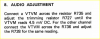
LH CH is set to 2.6 mVTo set bias, follow the directions from the service manual below. With power off, use minigrabber leads, if possible, to connect to each side of one of the resistors, R735 or R736. With input select set to Aux, volume at zero, balance centered, turn unit on. You should see mV DC on your DMM. If it is high, try turning the appropriate trimmer, R727 or R728 and watch the DMM. Try to set it at 4.5 mV. When setting bias, it tends to rise slowly for about 15 minutes, so you have to watch and reset during that time until it stabilizes. If bias will not set close to spec, something is wrong, and diagnosis is needed. Always attach and remove test leads with power off to prevent shorts. Good luck!
View attachment 2065623
Yes, BIAS is always 0 on RH channel. No changes if i turn R728.I would sure replace any component that I knew had gotten very hot during a short situation. Are you saying right channel bias is always 0 as you turn R728? If so, that is the reason the right channel is distorted. But the problem could be anywhere. C722 could be it, but pretty much everything on that side needs to be tested if changing C722 doesn’t fix it.
I'll try to change the caps then.It's definitely possible. Caps are at the bottom of my list of suspects usually, but in a situation where there has been short damage, they are candidates.