• The move to the new server is done. There are some software and database maintenance updates in process. This has us passing the hat around to help out. We appreciate any donations. Seriously, even a dollar helps. The payment page may be found here - https://www.audiokarma.org/support.html

Marantz 2220B bad J812 and J808 Voltage

Yahn

New Member
Howdy,

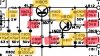
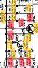
Still working on my receiver after replacing some components in the PSB already. What's replaced is shown in yellow and what's not been replaced is shown in red.

I am getting a reading of ~5V @ J808 and ~5V @ J812. Per the manual J812 should be getting 35V and J808 should be getting 14V. What could be the problem, since all the other pins have perfect voltage on them?

Some more information.: before H805 i am getting 48V and afterward I am getting 5V in both directions. H806 gives me 5V in all B/C/E.

I tested:
R803 at it came out 1.5k ohm
R804 tested at 1.5k ohm
R805 tested at 330 ohm
R801 tested at 22 ohm
R806 tested at 26k ohm - Much lower than the 36k it was supposed to be.
R807 tested below what it was meant to be.

I tested R806 and R807 on the circuit so these may be lower due to resistor math.

Any thoughts?

Much appreciated,
Jan
 
Register to hide this ad
Are you measuring between J811 and J812 when you look for the 35V DC? If you adjust R808 trimmer, does the value change? Checked fuse F801?
 
Last edited:
Both of those voltages are regulated and H807 Zener is the common denominator. Check the Zener and capacitors C807 and C809 for shorts.

Craig
 
Replaced H807. I ordered a couple of them and have tried both.

Will adjust the trimming resistor and check for shorts on C807 and C809. Will report back when I do.
 
If either voltage on J808/J812 is being loaded down somewhere in the receiver you'll also get the results you have. That 14VDC needs to be there in order to get the 35VDC but you have to have more than 14VDC on the emitter of H805 for any of it to work. You can try disconnecting the wires on J808/J812 to see if the voltages pop up.

Craig
 
Last edited:
pulling wires on pin J812 did not alter the voltages on either J812 or j808.


With all the wires pulled from J808 the voltage at J812 and J808 become 14VDC and 14VDC.

So when I pulled the wire that connects J808 to J302 the voltage at J808 became 10v. And also when I pulled an additional wire connecting J808 and J209 the voltage dropped to 5V.

Summary: I am not getting 35VDC at J812 no matter if I pull wires from J812 or J808. AND voltage across J808 becomes 14.7V if wires connecting J302 & J209 are pulled with wires at J812 connected.
 
Also, I checked the orientation of the output transistors and noticed in the manual they are opposite my configuration. However this receiver at one point worked with this orientation, though not well. I interchanged them to match the way the manual has them, and kept blowing fuses this way.
 

Attachments

  • F08DEBDC-B659-4E35-9C16-850FCDCB0180.jpeg
    F08DEBDC-B659-4E35-9C16-850FCDCB0180.jpeg
    63 KB · Views: 16
Something is loading down the voltage at J808 because your 14VDC supply came up and now the reference for the 35VDC supply is good also. Leave J808 disconnected and check the voltages on BCE of H805 and H806. The base of H806 should be adjustable.
 
So with all the wires at J808 disconnected I measured the voltage on each H805 and H806.

They are
H805
B: 15.3
C: 47.5
E: 14.8

H806
B: 15.3
C: 47.5
E: 14.8

And I adjusted the trimming resistor all directions and the “B” of H806 remained at 14.5VDC...
 
The base of H805 and the collector of H806 are connected together so they should have the same voltage. Double check your measurements and the installation of the transistors.

Craig
 
The base of H805 and the collector of H806 are connected together so they should have the same voltage. Double check your measurements and the installation of the transistors.

Craig


Craig I mistakenly copied the readings from my paper. You are correct.

My actual readings are

H806:
B 14.5
C 15.3
E 14.5

H805
B 15.3
C 47.5
E 14.8

I tested C807 and C809 and I couldn’t get any of them to show any signs of life when disconnected from the circuit. 0 resistance when connected to a multimeter in any setting. When connected in circuit I can measure increasing resistance when on a high ohm setting.
 
When checking over my previous recap work I saw that C810 was a 10V 1000 uF cap and I installed a 25V 1000uF cap. Could this be the culprit?
 
We know C807/809 are not shorted since the 14V came up when the wires on J808 were lifted. The base and emitter of H806 are the same voltage and that doesn't work for me, should have approx. .6VDC difference. And the fact that the base doesn't change when the pot is twiddled looks like H806 is shorted, installed incorrectly, something wrong there.

Going up in voltage on the capacitor is no problem.

What are voltage drops across R806/7?
 
Hate to dip in here, but possible H806 is not installed correctly. The normal ksc945 is EBC pinout. The center collector model, which is what you’d want based on your board and that location, has a “C” suffix (ksc945cyta not ksc945yta). Can you verify which one you bought and the correct pinout?

Mike
 
Back
Top Bottom