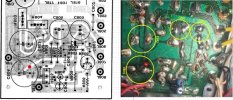
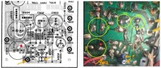
• The move to the new server is done. There are some software and database maintenance updates in process. This has us passing the hat around to help out. We appreciate any donations. Seriously, even a dollar helps. The payment page may be found here - https://www.audiokarma.org/support.html

Marantz 2220b came back after a recap with pesky power supply issues!

sean sweeney

AK Subscriber
Subscriber
I just recapped and calibrated this 2220b... found all the corrections, got the thing done, and when I fired it up, the 220 ohm wire wound resistor got hot and it blew the fuse. Still had the relay closing. Still had lights... so I went and did the calibration again and this time it all worked and did so for a solid week... but came back yesterday, and of course first thing I checked was that fuse. Which of course was blown. I put another one in and use the current limiter, and saw the resistor getting hot again. I checked the wires leaning out to the various other boards and saw nothing that would warrant attention.

Most of those boards have been recapped as well. So I thought maybe the regulating transistors were to blame, the larger one had some pretty disparate voltage drops on the various legs, so I replaced that. Still have that issue.

Trying to hunt it down but it's proving to be a little bit difficult. I know there's some folks here that probably have a better idea on how to troubleshoot this particular power supply. And I'll share whatever knowledge or whatever works and make sure this is one that's actually finished and show my work, so it can be added to the base of knowledge...

I was trying to trace where the voltage was going wrong, but as I had the adjustment pot all the way down, this crazy thing happened between the legs of one of the large filter caps on the board... I quickly turned it off but it was still doing whatever it was doing! It looked like a plasma Ray or something! It was some part of the board between the two pads for that capacitor, I guess had gone semiconductive, but where the electricity was coming from was a bit of a mystery, aside from Maybe some being stored in the capacitors of course. But that seems a little excessive!

I managed to film the tail end of it as I was tapping it with the probe. It's just kind of crazy because it was terribly bright, and throwing off little Sparks as if it was maybe gunpowder or something. Maybe the Silicon had just been slowly baked for years and years until it became combustible?

But in any case I'm still trying to figure out what the heck is going on with this thing. It was a great sounding unit for a week there and I'm not sure what the heck could have gone wrong. Especially when it was doing that at first and then stopped doing it and then started up again.

I disconnected the other boards to see if the voltages were affected and that wouldn't change anything. Now I'm just wondering where to go first and how to test the darn thing. And what's the safest way to do this and not damage the board anymore. Appreciate any help and as I said I will show everything and the eventual cure so people don't come in ask the same question over and over. Hopefully. LOL

To clarify, I adjusted and calibrated the power amp, using the corrected procedure listed here, as well aa the power supply, which also warranted a corrected procedure as the screen printing on THAT was also messed up.

I recapped, and also replaced the.larger transistor regulator, and replaced all the rectifier diodes. I didn't replace any of the zener diodes, as they didn't appear to be bad and I didn't have any replacements handy that would work for those, but they seem to be just fine. I even removed them and checked with them removed as well. I made a little movie that caught the end of that interesting dumpster fire! LOL


[https://archive.org/details/1209-01-1765303794701 width=560 height=384 frameborder=0 webkitallowfullscreen=true mozallowfullscreen=true]
 
Last edited:
Register to hide this ad
Check to make sure that C804 is installed with the correct polarity. Once the arcing started there could have been a carbon trace between the two board traces (41V) that caused it to continue to arc. Pull and check C804 for a short. Did you replace C804?

Screenshot 2025-12-09 230226.jpg
 
That board is an absolute mess. The soldering is atrocious, potentially unsafe, dangerous and as for the (now) combusting PCB, that small section needs to be removed. By removed, I mean drill a hole larger than the blackened part and clean it out. There's plenty of copper so it will be fine.

I can see myriad other poor soldering and semi-lifted/dry joints etc.
 
Yes, I did replace c804. The poster after you is calling out how the thing looks, but that's what I did in 10 minutes, hoping it would correct whatever issue had arisen! Lol. The problem I'm facing now, is that there are many posts out there detailing the goofs in the original screen printing. For instance, this one HAS NO test terminal j812... I used the manual to find that. As for the polarity of that cap, I hope that's the thing. I had the manual and the posts on here regarding corrections. But it wouldn't surprise me if there were goofs on this one that no one caught yet. Though it's hard to fathom it working fine for nearly a week, with a big cap like that inverted. And yes, this is the second cap in that slot, as i replaced it, over taking any chance. It is oriented correctly. The main issue that happens at the moment is the 220 ohm wire wound is heating up very fast even with the current limiter. I'm thinking the big transistor/regulator may have an issue and am trying to hunt up a replacement. The small transistor was replaced. I don’t see any issues with the AC leads from the xformer, and nothing out of the ordinary pulling from the other boards. Just the 222 ohm heating up, and blowing the fuse if the current limiter isn't engaged.


Check to make sure that C804 is installed with the correct polarity. Once the arcing started there could have been a carbon trace between the two board traces (41V) that caused it to continue to arc. Pull and check C804 for a short. Did you replace C804?

View attachment 3651445
 
Check to make sure that C804 is installed with the correct polarity. Once the arcing started there could have been a carbon trace between the two board traces (41V) that caused it to continue to arc. Pull and check C804 for a short. Did you replace C804?

View attachment 3651445
Sorry, I meant 22 ohms. Was going for memory. I replaced it with a 5w 30ohm, because it had gotten a bit charred in the week it was gone.
 
A tip for you if you're using no lead solder... switch to 60/40 good old fashioned type! And a clear, well lit and cropped picture of the top side would be nice. What is the reference designator of the "big" transistor? If it is marked D221 or the like an OnSemi MJ15030 will do nicely.

EDIT: Make sure you follow the correct advice to get the charred board remedied.
 
The poster after you is calling out how the thing looks, but that's what I did in 10 minutes, hoping it would correct whatever issue had arisen! Lol.
He's right though. How are you supposed to know that you aren't causing the fault when your board looks like that? Before you do anything else, clean up that board and repair the damage.
Also, I watched part of your vid and noted your cheap probe lead. Here's how to improve it:
Cut the ring off the front of it and sand it smooth. Sharpen the tip to a very fine point, as sharp as a fish hook if you can. Insulate the tip with heat shrink, or a piece of the jacket stripped off a wire so that only the very point of that sharp tip is exposed.
 
I'm not sure what you mean about J812?
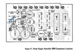
Here it is on your board photo and board layout from the SM. The orange arrow points to J812.
Also, what are those components attached to the back side of the board in series (orange arrows with ?)

Screenshot 2025-12-17 081507.jpg
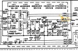
Here it is on the schematic from the SM.
Screenshot 2025-12-17 081934.jpg
 
He's right though. How are you supposed to know that you aren't causing the fault when your board looks like that? Before you do anything else, clean up that board and repair the damage.
Also, I watched part of your vid and noted your cheap probe lead. Here's how to improve it:
Cut the ring off the front of it and sand it smooth. Sharpen the tip to a very fine point, as sharp as a fish hook if you can. Insulate the tip with heat shrink, or a piece of the jacket stripped off a wire so that only the very point of that sharp tip is exposed.
The work in question here is temporary, and only been done since trying to find the issue. Experience has me doing this, rather than running the risk of damaging the weak traces on this from multiple attempts, trying to find the problem. It's not out of laziness. Putting components on the bottom isn't where they will stay. The components below are hooked up correctly, so that won't be an issue... everything will look as it should when I figure out where the issue is. I don't use lead free solder. Everything will be carefully replaced in the end. Right now I'm in breadboard mode! Lol.
 
I'm not sure what you mean about J812?
Here it is on your board photo and board layout from the SM. The orange arrow points to J812.
Also, what are those components attached to the back side of the board in series (orange arrows with ?)

View attachment 3656365
Here it is on the schematic from the SM.
View attachment 3656368
Here. Check the pic. There is no J812 on this board, but i found it via the manual. It just led me to wonder, when all the corrections were being made, if this was a variant that no one had seen yet. Pretty big goof on the board, if you didn't have the full manual back then! I blacked out the top of those caps, as they were showing too much glare.
 

Attachments

  • 20251220_150212.jpg
    20251220_150212.jpg
    177.2 KB · Views: 14
Seriously, I appreciate the help. I rarely ask for it, but follow up when I have an issue so that hopefully whetever issues I've had won't be asked about repeatedly. Thanks.
 
Oh... and just realized I hadn't subscribed. Very happy they upgraded. I can't tell you how many times I was writing something in here and went to grab a screen shot or look something up, and found an hour's worth of text "poofed". So glad there is a place like this, still. I'm kind of spread thin... I'm a pro musician, studio owner, hammond tech, and restore pro gear, amps, instruments, mods, and stereo/hifi is a hobby, and i can do the work, but sometimes struggle to understand some of what goes on in specifically MARANTZ pieces from the early Superscope days. Some of them look like aliens built them! The only thing stranger, I've found, is early analog synthesizers!! If you've ever worked on one... lol. They're not that crazy, in the end, but like the Marantz, they used a lot of "devices" made specifically for one task... that sometimes weren't even seen outside of that one synth! And the rules are different. Early synths are basically the sound of thousands of transistors, dying loud, agonizing deaths... and many of them take unusually high amounts of current! The prophet 5 I'm working on necessitates using a 300 watt bulb in the current limiter, or it won't initialize! I would love it, if I could just do any one of these things. But as it is, this area is sorely lacking for techs of any worth. I've got guys sending me mellotrons and leslies from LA and Hollywood! Apparently they have the same problem! So, sorry if I am a bit foggy on some of these. I like to understand the full theory of operation on sonething, which gradually happens when you take the time and work the same piece for a while... but I don't have that time at the moment, but I like to catch what I can. And again, I appreciate it.
 
He's right though. How are you supposed to know that you aren't causing the fault when your board looks like that? Before you do anything else, clean up that board and repair the damage.
Also, I watched part of your vid and noted your cheap probe lead. Here's how to improve it:
Cut the ring off the front of it and sand it smooth. Sharpen the tip to a very fine point, as sharp as a fish hook if you can. Insulate the tip with heat shrink, or a piece of the jacket stripped off a wire so that only the very point of that sharp tip is exposed.
Thanks, I improvised a new one shortly after that, which uses a tungsten stylus from an Edison gramaphone I'm also working on. That works better. And definitely, I have to buy a lot of shrink tube today. Since I made that video I restored a SHIN Ei Companion tape delay, circa 1967, and a Morkey oil can delay... as well as two Akai surround sound four tracks and a few guitars mods, and wurkitzer electric pianos. The problem I have is finding anything. I have 8 tube caddies... I couldn't find my regular meter, so I grabbed one without leads. I'm gonna order that transistor today, for the regulator. And fire this thing up after a complete rebuild, ignoring all but the schematic, since the screen writing on these seems to be hit or miss... then disconnect all of the boards it powers and monitor as I hook them up, once I establish proper voltages.
 
I learned very early on the value of insulated probe tips. The hard way. Zzzzap! Pow! Poof! Dammit!!!
 
I run into this with high-frequency RF gear.
The PWB has been reduced to charcoal, and carbon is conductive.
Two options, both involve cutting the blackened area fully.
1. Leave the hole. ( Airgap insulation )
If a trace crosses the hole, use appropriate guage, pvc insulated wire, or copper bus with heatsink.
2. Fill the hole with epoxy, and same advice on crossing traces.
IPA to clean any Flux, spilled soda, or PBJ from the affected area.
Keep us posted..
 
So I did drill out the charred area, using my Dremel and a mini-vac, and located a TIP41c in my parts supply. I saw another discussion on here, saying that transistor was a good match for the one in question in the power supply. I hooked it up, put some clips on the underside of the pbc, because I can't get enough purchase on the top of those little nibs, fired it up and right away, got 30v!! Ooh! Slowly rolled the pot up to 35v... and boom! It held! This is still with the current limiter hooked up, so i backed it down to 34, but there was no light at all in the limiter, and I'll try it again in a bit without the limiter. Might have gotten this sussed! I wasn't thinking it would work, as the transistor didn't appear to be bad when I removed it, but perhaps it was an "only under stess" thing *shrugs*
 
I run into this with high-frequency RF gear.
The PWB has been reduced to charcoal, and carbon is conductive.
Two options, both involve cutting the blackened area fully.
1. Leave the hole. ( Airgap insulation )
If a trace crosses the hole, use appropriate guage, pvc insulated wire, or copper bus with heatsink.
2. Fill the hole with epoxy, and same advice on crossing traces.
IPA to clean any Flux, spilled soda, or PBJ from the affected area.
Keep us posted..
This was a first for me! I wonder if this was truly the culprit all along. I mean, I wasn't really expecting that... I mean, so now I can't even trust silicone wafer board? Lol. And this was the section directly UNDER the capacitor between j811 & J812... only the section under that cap that became conductive. So I'm thinking it had become conductive before it started to smoke and burn, blowing the fuse, and the current limiter just allowed it to get hot enough to catch fire and start burning without blowing the fuse! This is a new one! So are you saying the high frequencies or just the constant heat or both, between that pad and the bottom of that cap, made this happen? I would imagine the copious amount of rubber cement didn't help, either, by enhancing the insulative, (heat insulation in this case) properties if the large capacitor, sitting over the two very oversized pads... likely oversized to disperse heat! Until they had reached a purity of blanched carbon that began to conduct! That is all new! There's a new one for the what can possibly happen file.
 
Historically, we X-ray the affected area to attempt to gain root cause.
Modern PWB are as dense as 10 layers, and at that density we battle cross talk, and failing VIAs due to thermal expansion..
 
So the Marantz is back with its owner. A few pics of the finished job. The transistor was changed to a TIP41c I believe. And the charred area removed. And whatever the cause, it was holding the voltage perfectly. Well, I guess the pic from the top didn't take! Lol.
Thanks again!
 

Attachments

  • 20251221_150815.jpg
    20251221_150815.jpg
    164.5 KB · Views: 18
Hello everyone, i recently recapped a Marantz 2220B, i noticed rapidly that the 330 ohms 2w resistor on R805 of the power supply is boiling hot, since before the recap. Also the transistor on H805 was running super hot. Finally i replaced most of the parts raised the 330ohms resistor to a 3w resistor and it still run very hot. all other hot running components previously are now ok, but the 330 ohms resistor, after around 5 seconds it's too hot to keep your finger on it. I also changed the other big resistor 220 ohms 2w, this one nothing wrong with it now or other parts than this hot R805 after the recap. Lack of experience makes me wonder, is it normal that it runs so hot? Just want to make sure not to damage anything. I have my 35V on it all other adjustments are on the nose too. Someone ever had the same situation, or knows more than me on resistor extreme heat running? Thanks !
 

Attachments

  • Capture d’écran 2026-02-28 115841.jpg
    Capture d’écran 2026-02-28 115841.jpg
    119 KB · Views: 2
Back
Top Bottom