• The move to the new server is done. There are some software and database maintenance updates in process. This has us passing the hat around to help out. We appreciate any donations. Seriously, even a dollar helps. The payment page may be found here - https://www.audiokarma.org/support.html

Marantz 2220b phono hum

dberry98

Member
First post from novice DIY. I replaced the lights and cleaned the connectors on my wife's original 2220b receiver and it sounds much better. During testing, I noticed a significant hum from the phono selector with no external turntable or other inputs attached. It was very noticeable at 1/4 volume and got much worse at 1/2 and in both channels. Switching to any other input (tape, aux, am, fm) and the hum goes away. I read this detailed post from another user with comments/instructions that said the following.

Did you check resistance between chassis and J403, J407, RCA Phono input connector & ground shield?
Cap C001 test OK?


A neighbor friend came by and did resistance check from J403 - J407 which was 0 but I'm not sure the other points we should check. We weren't able to check Cap C001 but it passes the eye test.

Any other thoughts or ideas? Thanks in advance for any comments. See attached pic.
 

Attachments
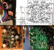
  • phono-pcb-all-pic.jpg
    phono-pcb-all-pic.jpg
    186.8 KB · Views: 12
Last edited:
Register to hide this ad
Hi and welcome to AK. Maybe if you can answer a few questions one of the members can assist you.
  1. Did the receiver have the hum before you worked on lights and cleaning?
  2. Which lamps did you replace and did you put in incandescent or LED bulbs?
  3. Did you replace ANY other components or unsolder any wires?
  4. Did you hear the hum with the cover on or off?
  5. Your resistance check from J403 to J407 is basically only checking the continuity of the ground plane on the P400 phono board. It does not test anything else. You want to measure the resistance from J403 to the chassis with power off and unplugged.
  6. Check the wire shields from the phono jack to J403 for L & R cables.
  7. With turntable attached, do you hear the hum?
  8. Do you have the receiver located near fluorescent or LED lighting strips or cellphone when you hear the hum?
 
Hi and welcome to AK. Maybe if you can answer a few questions one of the members can assist you.
  1. Did the receiver have the hum before you worked on lights and cleaning?
  2. Which lamps did you replace and did you put in incandescent or LED bulbs?
  3. Did you replace ANY other components or unsolder any wires?
  4. Did you hear the hum with the cover on or off?
  5. Your resistance check from J403 to J407 is basically only checking the continuity of the ground plane on the P400 phono board. It does not test anything else. You want to measure the resistance from J403 to the chassis with power off and unplugged.
  6. Check the wire shields from the phono jack to J403 for L & R cables.
  7. With turntable attached, do you hear the hum?
  8. Do you have the receiver located near fluorescent or LED lighting strips or cellphone when you hear the hum?
Thank you so much Dan for sharing your time knowledge.
1. not sure.
2. I replaced everything with the original incandescent bulbs EXCEPT the Stereo light which was not out and more importantly looked like it required some soldering.
3. No. The only solder I did was the tuning pointer light and I cheated and cut the old wire and connected it to the new one with a careful solder and double electrical tape. I had to replace the light fuse as well as (and this may be important), at one point when the top was off, it lost power and I had to replace the power fuse. After changing it, power was restored uneventfully but I don't know what caused it or if this did something to worsen the hum. I also spent a bit of time adjusting the tuner string as it was not aligned with the station frequencies. This required I loosen the 2 screws on the wheel attached to the tuner board and move the string without actully changing the tuner frequency.
4. Both on and off.
5. By chassis, would that be J403/7 to the J004 Gnd screw on the back. Any other? J401 or J402?
6. Ok. I'm assuming the wire shields are the outer most metal casing on external RCA phono inputs.
7. Yes, I hear the hum with turntable connected or not.
8. I've noticed the same hum in 2 different rooms. One, the AV room with lots of other gear and in the garage with virtually nothing else. I'll be sure to test without my phone nearby.

I'll try and do another test tomorrow since I don't have the meter. thnx again.
 
5. By chassis, would that be J403/7 to the J004 Gnd screw on the back. Any other? J401 or J402?
6. Ok. I'm assuming the wire shields are the outer most metal casing on external RCA phono inputs.
When I refer to the "chassis" it can be any metal part of the receiver structure that is not painted. Just clip the (-) lead of the DMM to this.
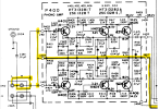
Here are the ground points on the phono board. But not J401 & J402, those are the L & R phono input signals from the turntable.
The little circle loop shown on the diagram depicts the wire shield.
Check carefully from the phono input connector to the solder points on the P400 board to make sure that a wire did not break off.
1708447753551.png

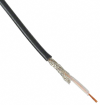
A shielded wire is one that has an inner solid or stranded wire covered with insulation then surrounded with a braid of wire that helps to prevent electrical interference both received and radiated from the wire. It will look something like this. The braided shield will probably be twisted together and covered with a shrink tubing to prevent shorting to other wires.
1708447313720.png
CAUTION: Do this with power off and AC cord unplugged from the wall. There is a potential shock hazard if you touch the wrong place. When you get the ohm meter (DMM) back, you should be able to set it to ohms, put one lead on the chassis then touch the other lead to the different shields and ground connections on the Phono board and should read close to 0 ohms.
 
Thanks for the info, prompt response, and your patience. Below are some resistance measurements with nothing attached and not plugged in to the best of my ability. I tested again with no phone nearby and it's basically the same.

J403 to J407: .2
J403 to chasis: .3
J403 to rca left shield: .3
J403 to rca right shield: .2
J403 - J004 (gnd screw): .7
J407 - J004 (gnd): .7
J407 - chasis: .4
J004 - rca left shield: .8
J004 - rca right shield: .7
J004 - rca phono ground (black) on inside of of connector (maybe J402): .7 (C001 capacitor between the 2)

Check carefully from the phono input connector to the solder points on the P400 board to make sure that a wire did not break off.
I saw no obvious wire issues and tried to test all those points.
 
Last edited:
so from a totally laymen's view, it appears C001 capacitor has some resistance, less than 1 ohm but is it enough to cause noticeable hum in the phone selector? Thanks in advance.
 
First post from novice DIY. I replaced the lights and cleaned the connectors on my wife's original 2220b receiver and it sounds much better. During testing, I noticed a significant hum from the phono selector with no external turntable or other inputs attached. It was very noticeable at 1/4 volume and got much worse at 1/2 and in both channels. Switching to any other input (tape, aux, am, fm) and the hum goes away. I read this detailed post from another user with comments/instructions that said the following.

Did you check resistance between chassis and J403, J407, RCA Phono input connector & ground shield?
Cap C001 test OK?


A neighbor friend came by and did resistance check from J403 - J407 which was 0 but I'm not sure the other points we should check. We weren't able to check Cap C001 but it passes the eye test.

Any other thoughts or ideas? Thanks in advance for any comments. See attached pic.
Put the covers back on, they are also hum shields. Phono inputs are very sensitive and when open (nothing plugged in) can pick up hum. That's why there are PHONO shorting plugs to prevent the hum. NOTE Phono shorting plugs are not to be used on AUX or other inputs. They do not need them.
 
Back
Top Bottom