• The move to the new server is done. There are some software and database maintenance updates in process. This has us passing the hat around to help out. We appreciate any donations. Seriously, even a dollar helps. The payment page may be found here - https://www.audiokarma.org/support.html

Marantz 2230 bulbs wiring

JDel

New Member
Hi,
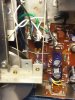
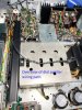
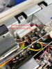
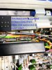
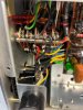
I found out that all the fuse lamps were replaced by led strips in the dial and in the meter . Both of the lamps holders are missing and the meter housing was cut open in the back. The function light board looks good. I have both holders and meter housing on order, should be here this week.

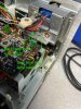
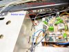
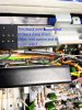
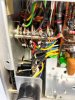
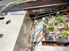
The wiring was modified, both green wires are attached to a junction board , a resistor and a capacitor are also part of that board . Beside dial pointer light everything lights up.

I would like to rewire everything back to original. But i need some help. This the canadian model with the 4 fuses holder, the schematic i have is for the US model.

Help would be greatly appreciated,

Thanks
Jean


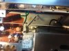
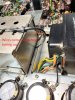
20201206_150641.jpg 20201206_152238.jpg
 
Register to hide this ad
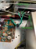
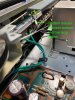
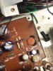
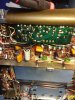
Somebody really messed that up. No need for that modification with modern LED’s that have the regulator built in. They are a drop in replacement for the incandescent. But... if you have new boards coming, we can help you wire it. The green wires carry about 7V AC directly from the transformer and connect to the lamp board's first lamp socket terminals. The five dial lamps and meter lamp are all in parallel from that point. Where the two green wires attach, one black wire daisy chains to each lamp socket all the way to the meter lamp socket. The other green wire has a grey wire attached that daisy chains to the other terminal on each lamp. There is an 18 ohm resistor connected between the bottom lamp board and the upper lamp board for the input select lamps. Hope this helps. If you have questions, let us know. BTW, this 2230 is a very late serial number, so it's possible there could be some differences. But I think yours will look like this.
Steve
2230 lamps 1.jpg
2230 Lamps 4.jpg
2230 Lamps 3.jpg
2230 lamps 2.jpg
 
That helps a lot, so i keep only the two green wires and start from there. There is a disconnected black wire, i guess comming from the dial indicator, where should i connect it? Same for black wire going to the input selector that will have to be removed from that junction board, where does it connect?
Thanks

20201209_190106.jpg
 
That helps a lot, so i keep only the two green wires and start from there. There is a disconnected black wire, i guess comming from the dial indicator, where should i connect it? Same for black wire going to the input selector that will have to be removed from that junction board, where does it connect?
Thanks

View attachment 2060549
I can't tell about the black wire. Can you take a pic of the other end, or at least where it disappears under something?
 
The disconnected black wire runs under P100 board and connect to the dial indicator
light.
20201210_224233.jpg

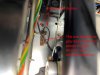
And the other black wire is routed loose thru the underside,which i think is wrong, connects to the input selector switch.
20201210_225052.jpg
20201210_231338.jpg
Thanks
Jean
 
There are two black wires that go to the dial pointer. They usually run from near the front, under the tuning cap, out the back under the tuning cap, then up and over the tuning cap to the dial pointer. They are twisted together and run through a black sleeve above the tuning cap. This awkward path gives the wires plenty of slack for horizontal movement without being in danger of getting tangled..I believe one of them ultimately goes to the input select switch, and one finds the 7V AC power at a terminal strip on the chassis. Replacements - either incandescent or LED - usually have two long wires coming out of the bulb to make that path. But I will open this one back up and see if I can verify.
 
I finally got a non-US schematic, few differences compare to the US version but for the section that i am concerned with, it is the same configuration. You are right. For the dial pointer one wire runs thru a jonction and then to the selector switch,the second one to a 7v AC power, probably from the lamp board.
The wire in the 2nd and 3rd pic, one end connect to the selector switch, according to the schematic, gets 7V AC from the lamp board . I think the lenght and the routing of the wire was modified to fit the messed up led mod. I should get the lamps holder today.
 
Sorry, forgot to specify that the wire on the 2nd and 3rd picture, is a wire removed from the led mod, it does'nt have nothing to do with the dial indicator, it runs straight to the selector switch.
 
More pics that I think will answer some questions:
2230 lamps 7.jpg
2230 lamps 8.jpg

Pointer wires at terminal strip between tuning cap and lamp board:
2230 lamps 9.jpg
 

Attachments

  • 2230 lamps 10.jpg
    2230 lamps 10.jpg
    109.6 KB · Views: 24
  • 2230 lamps 13.jpg
    2230 lamps 13.jpg
    119.6 KB · Views: 26
  • 2230 lamps 12.jpg
    2230 lamps 12.jpg
    121.4 KB · Views: 25
  • 2230 lamps 11.jpg
    2230 lamps 11.jpg
    114.8 KB · Views: 25
Last edited:
I appreciate your patience and support. Your explanations and pictures made it more concrete than the schematic itself. Very helpful and thanks again.
Jean
 
I appreciate your patience and support. Your explanations and pictures made it more concrete than the schematic itself. Very helpful and thanks again.
Jean
If questions pop up, let us know. I have this 2230 close by to check if needed.
 
As soon as i get the parts, i'll go at it and fix that mess. I will let you how it goes.
Thanks again,
Jean
 
The white wire on the terminal strip according to the diagram should go directly to the input selector at the first terminal toward the front of the selector.

PSX_20201211_183218.jpg
 
The white wire on the terminal strip according to the diagram should go directly to the input selector at the first terminal toward the front of the selector.

View attachment 2062386
You are absolutely correct, Sir. I pulled the covers again and used a little magnification this time. The white wire from the terminal strip touches the white wire to the stereo lamp, and a little tug on the end by the terminal strip caused a pull on the one to the stereo light. But indeed, it attaches where you pointed out. I'll edit my pics for future reference. Good catch! Thanks!
 
Can't add pics to a post, so removed the incorrect ones. Here are the ones related to the input select switch.
2230 lamps 10.jpg
2230 lamps 12.jpg
2230 lamps 11.jpg
 
Hi everyone,
After searching the web for the answer to my problem I stumbled upon this thread which helped me to understand a part of it, but still leaving me with a few questions.
So, my problem is that I got a LED replacement kit to replace the lighting on my 2230, and while at first I had success replacing the 5 bulbs inside the main lamp board, I messed up while trying to replace the one lighting the VU indicator (and stupidly doing that while having the receiver powered on). I must have touched something I shouldn't have with the tip of the screwdriver when trying to pull out the old fuse light which resulted in all of the lights except the STEREO indicator one not lighting up any more.
I haven't noticed any other damage to the receiver functions being that it still works, except that the lights don't. I also checked the 4 visible fuses (2x 0,5A, 2A, 3A) and none are blown.Also, I don't see any damaged/cut wires that would be of relevance.

So my question is if anyone could help me deduce where the problem could lie, as all of the lights are wired in parallel, and even if one of them blew, the rest should be working fine. I currently don't have the instruments to test the powering from the transformer, but if that turns out to be true, what would the fix be? Are there any additional fuses hidden somewhere that could have blown?
 
Last edited:
Hi everyone,
After searching the web for the answer to my problem I stumbled upon this thread which helped me to understand a part of it, but still leaving me with a few questions.
So, my problem is that I got a LED replacement kit to replace the lighting on my 2230, and while at first I had success replacing the 5 bulbs inside the main lamp board, I messed up while trying to replace the one lighting the VU indicator (and stupidly doing that while having the receiver powered on). I must have touched something I shouldn't have with the tip of the screwdriver when trying to pull out the old fuse light which resulted in all of the lights except the STEREO indicator one not lighting up any more.
I haven't noticed any other damage to the receiver functions being that it still works, except that the lights don't. I also checked the 4 visible fuses (2x 0,5A, 2A, 3A) and none are blown.Also, I don't see any damaged/cut wires that would be of relevance.

So my question is if anyone could help me deduce where the problem could lie, as all of the lights are wired in parallel, and even if one of them blew, the rest should be working fine. I currently don't have the instruments to test the powering from the transformer, but if that turns out to be true, what would the fix be? Are there any additional fuses hidden somewhere that could have blown?
The dial and VU meter lights get their power directly from the transformer, meaning it is AC voltage - around 7-8V. If yours has the fuses (not all version do), by far the best candidate is one of those fuses because one of them is there to protect against just such a short. I'm not sure which one it is, but I would pull them one at a time and double check with a DMM. I'll bet one of them is blown because there is only one component in that light circuit other than the lights, and it is the small resistor connected to one of the green wires behind the lamp board. Test the fuses off of the board, and if all test good, test that resistor. It is the 18 ohm resistor shown in the pic in post #2 of this thread.
 
Last edited:
Back
Top Bottom