• The move to the new server is done. There are some software and database maintenance updates in process. This has us passing the hat around to help out. We appreciate any donations. Seriously, even a dollar helps. The payment page may be found here - https://www.audiokarma.org/support.html

Marantz 2230 P800 Power Supply – J808 Stuck High (~43V), No Regulation from R810

Corky1998

New Member
Hi everyone,

I’ve been working on restoring the P800 power supply board on my Marantz 2230, and I’m currently stuck with a voltage regulation issue that I haven’t been able to resolve.

The main problem is that J808 is sitting far too high and cannot be adjusted. According to the service manual, J808 should be adjustable to 35.6 VDC, however I am measuring ~43 VDC on a dim bulb tester, and the trimmer R810 has no effect at all — the voltage does not move in either direction.

Below is a complete list of parts on the P800 board, indicating which parts were replaced and which were left original.

Resistors​

  • R801 10 Ω 1/2 W (no replacement made)
  • R803 3.3 kΩ 1/2 W (no replacement made)
  • R804 10 Ω 1/2 W (no replacement made)
  • R805 4.7 kΩ 1/4 W (no replacement made)
  • R806 1.5 kΩ 1/4 W (no replacement made)
  • R807 3.9 kΩ 1/2 W (no replacement made)
  • R808 27 kΩ 1/4 W (replaced with 27 kΩ 1/4 W)
  • R809 5.6 kΩ 1/4 W (replaced with 5.6 kΩ 1/4 W)
  • R810 4.7 kΩ (no replacement made)

Capacitors​

  • C801–C802 500 V 0.01 µF (no replacement made)
  • C803 63 V 470 µF (replaced with Nichicon 63 V 1000 µF)
  • C804 50 V 330 µF (no replacement made — part yet to arrive)
  • C805 16 V 470 µF (replaced with Nichicon 16 V 470 µF)
  • C806 50 V 330 µF (no replacement made — part yet to arrive)
  • C807 50 V 3.3 µF (replaced with Nichicon 50 V 10 µF)

Semiconductors​

  • H801 2SD315 (replaced with MJE15032G)
  • H802 2SC696 (replaced with MJE182G)
  • H803 2SC1213 (replaced with KSC2383YTA)
  • H804–H805 SIB-01-02 (replaced with UF4005)
  • H806 BZ-140 (replaced with 1N4744A)
  • H807 WZ-071 (replaced with 1N4737A)
With the unit powered on (DBT in place), I am seeing the following voltages:
  • J808: ~43 V (should be 35.6 V, not adjustable with R810)
  • H802:
    • Collector: ~46 V
    • Base: ~43.6 V
    • Emitter: ~42.9 V
  • H803:
    • Collector: ~43.7 V
    • Emitter: ~7.4 V
    • Base: 0 V
From what I understand, H803 is the error amplifier that drives the regulation, and the fact that its base is sitting at 0 V while the collector is near raw B+ makes me suspect this stage is not operating correctly. That said, I am confident that H803 (KSC2383YTA) is installed in the correct orientation, and I have verified the pinout against the datasheet.

Any insight into what could cause no regulation action at all at J808, especially with these voltage readings, would be greatly appreciated.

Thanks in advance for any help.
 

Attachments

  • tempImageDdzVVE.jpg
    tempImageDdzVVE.jpg
    77.7 KB · Views: 15
  • tempImagef5ZQOp.jpg
    tempImagef5ZQOp.jpg
    114.6 KB · Views: 15
  • tempImagePbXvJy.jpg
    tempImagePbXvJy.jpg
    126 KB · Views: 15
  • Like
Reactions: mbz
Register to hide this ad
First question, did it work before you started in?

Some basics, measure the carbon comp resistors in circuit, are they in spec.

You used a 14V and a 7.1V zener, to be clear?

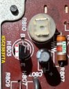
Can you post a pic of H02 that shows the face of the transistor and the board markings.
 
First question, did it work before you started in?

Some basics, measure the carbon comp resistors in circuit, are they in spec.

You used a 14V and a 7.1V zener, to be clear?

Can you post a pic of H02 that shows the face of the transistor and the board markings.
Hi Warren-Oates.

Thanks for your reply! It is very much appreciated :)

Yes, the unit was working before I started the restoration and still plays music, so the only issue now is the overvoltage. I measured the carbon composition resistors in-circuit, and most are reasonably close to their nominal values, though a few have drifted slightly. For reference, the nominal values and my measurements are:

R801 10 Ω → 10.3 Ω
R803 3.3 kΩ → 3.97 kΩ
R804 10 Ω → 11.3 Ω
R805 4.7 kΩ → 4.72 kΩ
R806 1.5 kΩ → 1.54 kΩ
R807 3.9 kΩ → 4.46 kΩ
R808 27 kΩ → 27 kΩ (replaced)
R809 5.6 kΩ → 5.6 kΩ (replaced)

Regarding the zener diodes, H806 was replaced with a 1N4744A (15 V, 1 W) and H807 with a 1N4737A (7.5 V, 1 W), and I apologise for not specifying this earlier. I’ve also attached two photos of H802 showing both the transistor face and the board markings for reference.
 

Attachments

  • tempImage5rfylF.jpg
    tempImage5rfylF.jpg
    120.6 KB · Views: 6
  • tempImagePVZqQS.jpg
    tempImagePVZqQS.jpg
    144.1 KB · Views: 6
To be more specific, the unit had adjustable voltage before you started? If so it has to be an issue with what you have done.

Or it played music but the voltage did not adjust? Then you started your repair of the PS.
 
To be more specific, the unit had adjustable voltage before you started? If so it has to be an issue with what you have done.

Or it played music but the voltage did not adjust? Then you started your repair of the PS.
Yes, the voltage was fully adjustable before I started, so it seems this overvoltage issue has arisen during the restoration process. Overall, the unit was in full operational order, although I had previously noticed an intermittent left channel issue, which I had attributed to something in the power amp section that I plan to address later. Thank you very much for your guidance and for taking the time to help me troubleshoot this. I really appreciate it!
 
Ok, it "should be easy" to figure out as you have not done much.

  • H801 2SD315 (replaced with MJE15032G)
  • H802 2SC696 (replaced with MJE182G)
  • H803 2SC1213 (replaced with KSC2383YTA)
  • H804–H805 SIB-01-02 (replaced with UF4005)
  • H806 BZ-140 (replaced with 1N4744A)
  • H807 WZ-071 (replaced with 1N4737A)

H801 should only go in one way, so I don't think you could make a mistake there, collector making contact through screw?
H802 MJE182G, pinout is ECB, I assume, did you verify? how much gain does it have? Could try putting old part back in. Tip31C may be better gain wise
H803 should be fine
H804,05 follow board markings?
Zeners, any chance you switched the two values around?

Just a few thoughts, as it has to be something you just did

Measuring Jumper J08 and to chassis ground with other probe, right?
 
  • Like
Reactions: mbz
Ok, it "should be easy" to figure out as you have not done much.

  • H801 2SD315 (replaced with MJE15032G)
  • H802 2SC696 (replaced with MJE182G)
  • H803 2SC1213 (replaced with KSC2383YTA)
  • H804–H805 SIB-01-02 (replaced with UF4005)
  • H806 BZ-140 (replaced with 1N4744A)
  • H807 WZ-071 (replaced with 1N4737A)

H801 should only go in one way, so I don't think you could make a mistake there, collector making contact through screw?
H802 MJE182G, pinout is ECB, I assume, did you verify? how much gain does it have? Could try putting old part back in. Tip31C may be better gain wise
H803 should be fine
H804,05 follow board markings?
Zeners, any chance you switched the two values around?

Just a few thoughts, as it has to be something you just did

Measuring Jumper J08 and to chassis ground with other probe, right?
Yes, J808 is being measured with respect to chassis ground.

I agree with you regarding H801, it really only fits one way, and the collector is making proper contact through the mounting screw, so that one appears to be fine.

For H802, yes, I concur that the MJE182G pinout is ECB. I verified this against the Mouser datasheet prior to installation. I didn’t check the gain, to be honest, but I can certainly try reinstalling the original part to rule that out, or look into using a TIP31C as you suggest.

H803 does seem fine, and based on the photos I’ve just posted, H804 and H805 appear to be installed correctly and follow the board markings.

Regarding the zeners (H806 and H807), there is a possibility that I may have switched H806 and H807, although I’m fairly sure I checked this carefully at the time of installation. That said, I will double-check this as soon as I have the opportunity.

Thank you very much for taking the time to go through this and for your suggestions, I really appreciate the help. I’ve been scratching my head over this for days, so having another experienced set of eyes on it is very helpful.
 

Attachments

  • H801.jpg
    H801.jpg
    197 KB · Views: 8
  • H804 and H805.jpg
    H804 and H805.jpg
    206.8 KB · Views: 7
  • H806.jpg
    H806.jpg
    209.1 KB · Views: 7
  • H807.jpg
    H807.jpg
    246 KB · Views: 7
  • H803:
    • Collector: ~43.7 V
    • Emitter: ~7.4 V
    • Base: 0 V
From what I understand, H803 is the error amplifier that drives the regulation, and the fact that its base is sitting at 0 V while the collector is near raw B+ makes me suspect this stage is not operating correctly. That said, I am confident that H803 (KSC2383YTA) is installed in the correct orientation, and I have verified the pinout against the datasheet.
H803b "cant" be 0V, your thinking above is correct, need to work out why 0V, possible burnt track? or solder joint or...

edit maybe faulty wiper on R810??
 
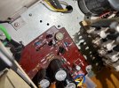
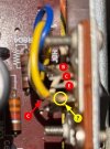
Your photo is very blurry, could you please verify the ECB wiring from the transistor to the PC board or post a better photo of the wiring from the H801 leads to the PC board?
  • It looks like the yellow wire is connected to the heatsink, where does the other side go?
  • The white wire looks like it is connected to the H801 collector lead and goes to C804(+).
  • I blue wire looks like it connects to H801 base but I can't see where it goes.
  • I can't see a wire connected to the H801 emitter pin?
Screenshot 2025-12-24 095817.jpg__Screenshot 2025-12-24 101425.jpg
Screenshot 2025-12-24 101830.jpg
Also, please check leads on H803. It's hard to tell from your photo. The leads should not be crossed.
Screenshot 2025-12-24 122638.jpg
 
Last edited:
Your photo is very blurry, could you please verify the ECB wiring from the transistor to the PC board or post a better photo of the wiring from the H801 leads to the PC board?
  • It looks like the yellow wire is connected to the heatsink, where does the other side go?
  • The white wire looks like it is connected to the H801 collector lead and goes to C804(+).
  • I blue wire looks like it connects to H801 base but I can't see where it goes.
  • I can't see a wire connected to the H801 emitter pin?
View attachment 3661479__View attachment 3661486
View attachment 3661488

Hi Dankik, thank you very much for taking the time to look at this and for all the help so far, I really appreciate it. Sorry about the blurry photos, I’ll try to take clearer ones if needed.

To clarify the wiring: there are three wires going from the PCB to H801:
  • Base (B) → blue wire (marked “B” on the PCB, visible in the photo)
  • Collector (C) → yellow wire (the yellow wire you see near the heatsink)
  • Emitter (E) → white wire (visible in the photo)
On the underside of the PCB, the Emitter (E) pad has a blue wire that goes directly to the brown grounding piece (chassis ground).
For Base and Collector, on the underside there are no wires, only solder pads.

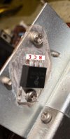
Regarding the H801 replacement (MJE15032G): since the original heatsink only has two holes, I cut off the Collector lead and only passed Base and Emitter through the heatsink holes. Because of this, there are no wires soldered directly to the MJE15032G leads on the other side of the heatsink—all connections are made through the PCB wiring described above.

Thanks again for your patience and guidance, it’s been extremely helpful while working through this.
 

Attachments

  • tempImagewmP6sE.jpg
    tempImagewmP6sE.jpg
    204.9 KB · Views: 8
  • tempImagemu5rLs.jpg
    tempImagemu5rLs.jpg
    217.8 KB · Views: 9
  • tempImagemBMWsG.jpg
    tempImagemBMWsG.jpg
    220 KB · Views: 7
  • tempImageljXy0K.jpg
    tempImageljXy0K.jpg
    180.5 KB · Views: 7
With amp powered off measure resistance between R810 wiper (middle leg) and one of the outer legs, repeat for wiper and other outer leg, OL indicates open.
 
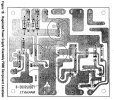
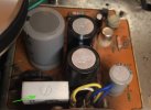
Why is it your P800 board does not have this large 150 Ohm 5W ceramic resistor (R018)?
On the schematic, it shows it off-board on a terminal standoff (J021), but on other photos of the board it is shown mounted on the P800 board. I think I see the standoff on the bottom side of the chassis on one of your other photos.
Marantz 2230 Receiver Restoration

Screenshot 2025-12-24 125432.jpg

You can see it on another photo here also. Maybe someone else knows why?
Screenshot 2025-12-24 130330.jpg
 
Last edited:
Why is it your P800 board does not have this large 150 Ohm 5W ceramic resistor (R018)?
On the schematic, it shows it off-board on a terminal standoff (J021), but on other photos of the board it is shown mounted on the P800 board. I think I see the standoff on the bottom side of the chassis on one of your other photos.
Marantz 2230 Receiver Restoration

View attachment 3661608

You can see it on another photo here also. Maybe someone else knows why?
View attachment 3661613
There it is. Underneath, I've seen that in many units.
 

Attachments

  • tempImagef5ZQOp.jpg
    tempImagef5ZQOp.jpg
    113.7 KB · Views: 16
With amp powered off measure resistance between R810 wiper (middle leg) and one of the outer legs, repeat for wiper and other outer leg, OL indicates open.
Thanks for the clarification mbz. It is very much appreciated!

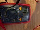
With the amp powered off, I identified the three solder joints corresponding to the R810 trimmer. Measuring resistance between the wiper (middle leg) and the outer legs, the only combination that gives a resistance reading is the one shown in the attached photo, which measures 78.6 Ω.

When measuring the wiper against the other outer leg combinations, the meter shows OL.

Using that same valid combination:

  • Turning the trimmer fully clockwise gives about 0.19 Ω
  • Turning it fully anticlockwise results in OL
Is this behavior normal for this type of trimmer?

I understand that R810 is used to trim the voltage by a few volts, and I agree the trimmer itself could be faulty. However, I’m struggling to reconcile how a bad trimmer alone could explain the voltage being so far off:

  • With DBT, I’m seeing about 43 V where the service manual specifies 35.6 V
  • Without DBT, this rises closer to 45 V
That seems like a much larger deviation than what R810 should be responsible for correcting on its own, so I’m wondering if something else in the circuit may also be contributing.

Any thoughts appreciated.
 

Attachments

  • 2025-12-26 at 15.00.02 copy.jpeg
    2025-12-26 at 15.00.02 copy.jpeg
    136 KB · Views: 7
  • 2025-12-26 at 15.00.02 copy.jpeg
    2025-12-26 at 15.00.02 copy.jpeg
    135.1 KB · Views: 7
Do you have to select the range on the meter or does it have the "auto range" feature? If you have say the 200 ohm range, it will go to OL most likely.
 
  • Like
Reactions: mbz
Do you have to select the range on the meter or does it have the "auto range" feature? If you have say the 200 ohm range, it will go to OL most likely.
My multimeter is not auto-ranging, I have to select the range manually.

For these measurements I had it set to the 200 kΩ range.
 
Last edited:
However, I’m struggling to reconcile how a bad trimmer alone could explain the voltage being so far off:
The problem is H803 base voltage = 0V.
H803 is somewhat of a feedback mechanism, taking the J808 voltage and then fine tuning.
J808 voltage is set by H802base which in turn is set by current flow/volt drop through R805,6.
That current flow is controlled by how hard H803 is on (Vbe), H803 is off since Vb=0 so no current flow (uA?)
so no volt drop. So you end up with H802Vc = Vb (almost since uA leakage)
 
My multimeter is not auto-ranging, I have to select the range manually.

For these measurements I had it set to the 200 kΩ range.
Sounds like the pot is bad unless a parallel component is affecting the reading. You'd have to unsolder and remove the pot to be sure. Have you measured the voltage on the pot's wiper/center terminal as you are adjusting it?
 
Back
Top Bottom