• The move to the new server is done. There are some software and database maintenance updates in process. This has us passing the hat around to help out. We appreciate any donations. Seriously, even a dollar helps. The payment page may be found here - https://www.audiokarma.org/support.html

Marantz 2238 won't power on.

Aaron99

Active Member
New to the forum. I just acquired a Marantz 2238 in decent cosmetic shape from a seller on CL. The seller told me that when he presses power button a few seconds later he hears a click and then nothing.

The unit passed a DBT and then I plugged it in and powered on. Within 2 or 3 seconds heard the relay click and then nothing.
I then went to test the power supply board.
I unplugged the unit and clipped my DMM onto J805 and J814. I powered on the amp and after the click, the voltage measured about 6V. I tried to adjust R808 and it only varies from 5V to about 6.5 V. Could this be capacitors on the power supply board? What else should I test?

I just recently got bitten by the Marantz bug.
 
Register to hide this ad
My diagnostic skills are in the novice stage, but here's the best I've got. You can go through the schematic, checking voltages where listed and see if they are down everywhere - or where they begin to be low. The transistor legs would be a good place to start. I'm assuming you know to tape probes all except the tip or use mini-grabbers so you don't short anything out. Another approach would be to replace all of the electrolytic caps, since it's a dumpster unit and you need to do that anyway, and see if anything changes. The unit is off the DBT, right? The AC input voltage at J801/802 would be nice to know, but I don't see it on the schematic. But if it was very low - like under 10v, that might mean bad transformer (uncommon, but again -- dump unit). Anyway, just my random thoughts. Hoping someone more experienced will point you more in the right direction
Steve
 
My diagnostic skills are in the novice stage, but here's the best I've got. You can go through the schematic, checking voltages where listed and see if they are down everywhere - or where they begin to be low. The transistor legs would be a good place to start. I'm assuming you know to tape probes all except the tip or use mini-grabbers so you don't short anything out. Another approach would be to replace all of the electrolytic caps, since it's a dumpster unit and you need to do that anyway, and see if anything changes. The unit is off the DBT, right? The AC input voltage at J801/802 would be nice to know, but I don't see it on the schematic. But if it was very low - like under 10v, that might mean bad transformer (uncommon, but again -- dump unit). Anyway, just my random thoughts. Hoping someone more experienced will point you more in the right direction
Steve

Steven, Thanks for the reply. I did put my DMM into ACV and measured pins J801 and J802. It measures 39.9ACV.
 
That sounds about right from what I have seen on other units. Honestly, because of my novice diagnostic skills, I would recap it before doing anything else. You may just have a bunch of really bad caps. More experienced people would likely start working through measurement points and find where low voltages start. But since it needs a recap anyway, that's an easy start. Also, look for any sign of really hot components. Sometimes a failed resistor will damage downstream semiconductors.
 
relay clicking is a good sign .. dont go swapping out things just yet .. be sure any jumpers if needed are in place first and all switches are set correctly .
 
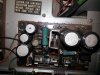
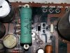
Thanks for responding Steve, and Pete. I just noticed something on backside of the cover that I didn't notice before. It looks like it has smoke stain about 3 inches by 3 inches from the front right. This would place it right above the P800 power supply board. I see some slight damage behind the heatsink and resistor. I looked very closely at the backside of the P800 board and noticed what looks like non stock soldering of what would be Q803 Transistor. Right now it contains a Sanyo D330 E6M. Is there anyway to test the transistor without desoldering it from the board?
 
I think you have to pull it to test it properly. If you do pull it, pay close attention to which leg goes where (E, C and B). If you haven't tested one before, read Echowars great tutorial. You use the diode test function on your DMM and this is an NPN transistor.

http://audiokarma.org/forums/index.php?threads/bipolar-junction-transistor-testing-basics.43186/

Thats a great tutorial.

I just pulled Q803 and every way I test the transistor I get OL for all test conditions when using the Diode test function.
B ->E = OL
B ->C = OL
E ->B = OL
C ->B = OL
C ->E = OL
I think it is dead. What would be a good replacement for the D330 E6M? The service manual lists it as a 2SD330 D or E. Would the modern equivalent be the MJE15030 at Mouser? If I order that I think I should replace all the electrolytic capacitors on the P800 to make the order worth while.
 
The 15030 is a great sub for that part. See what is burned before any power on with a new part. I also highly recommend you recap this board. I like Nichicon HE and PW series in power supplies. I also like to go up a voltage rating level, like on a 25V part, use a 35V replacement.
 
The 15030 is a great sub for that part. See what is burned before any power on with a new part. I also highly recommend you recap this board. I like Nichicon HE and PW series in power supplies. I also like to go up a voltage rating level, like on a 25V part, use a 35V replacement.

Nothing else seems burnt on the power supply board. I am thinking of replacing the resistors too. Any thoughts on that?
Do these seem like good replacements for the caps?

Location Original Replacement MouserPart#
C802 470uF 63V 470uF 63V UPW1J471MHD3
C803 470uF 63V 470uF 63V UPW1J471MHD3
C804 100uF 50V 220uF 50V UPW1H221MPD
C807 3.3uF 50V 10uF 50V UPM1H100MDD
C808 470uF 16V 470uF 35V UPW1V471MPD
C809 1000uF 10V 1000uF 50V UPW1H102MHD
 
I would make a sketch of each electrolytic cap, noting polarity as found and the actual value on the part. Then remove all the caps and the bad transistor. Clean off the burn spot and dig out the pc board material if it is burnt too as that can be conductive and cause mayhem. If it needs dug out deep, fill the crater in with some clear 5 or 12 minute epoxy.

Then measure all of the resistors to see what the values are, just don't change them. Now if they look cooked, it wouldn't hurt to replace them. I don't see any in your picture but it's pretty dark on my screen.

The replacements look good with the exception of C804 going from 100uF to 220uF. That won't help any and will cause the 35V supply to come up more slowly and maybe cause issues. Maybe not!
 
I would make a sketch of each electrolytic cap, noting polarity as found and the actual value on the part. Then remove all the caps and the bad transistor. Clean off the burn spot and dig out the pc board material if it is burnt too as that can be conductive and cause mayhem. If it needs dug out deep, fill the crater in with some clear 5 or 12 minute epoxy.

Then measure all of the resistors to see what the values are, just don't change them. Now if they look cooked, it wouldn't hurt to replace them. I don't see any in your picture but it's pretty dark on my screen.

The replacements look good with the exception of C804 going from 100uF to 220uF. That won't help any and will cause the 35V supply to come up more slowly and maybe cause issues. Maybe not!

Thanks for the feedback. I will try and clean up the board where it got hot. I will post a picture.

Here is the latest shopping list.

Location Original Replacement MouserPart#
C802 470uF 63V 470uF 63V UPW1J471MHD3
C803 470uF 63V 470uF 63V UPW1J471MHD3
C804 100uF 50V 100uF 63V UPW1J101MPD
C807 3.3uF 50V 3.3uF 50V UPW1H3R3MDD
C808 470uF 16V 470uF 35V UPW1V471MPD
C809 1000uF 10V 1000uF 50V UPW1H102MHD
Q803 (Transistor 2SD330 D or E) MJE15030

Do you usually find it necessary to replace the DS132B and DS131B diodes when rebuilding a board? I think I would like to replace them but I can not figure out the replacement part number. I read on another thread that BYQ28E-200,127 might be a replacement for Q802, or DS131B. What would the replacement be for DS132B? I read somewhere where I could alternately use two 1N4007 diodes for each of them and orient them accordingly.
Location Original -> Replacement
Q801 DS132B-> ???
Q802 DS131B -> BYQ28E-200,127

I measured the resisters in circuit. I'm not sure I can trust the measurements because it is in circuit, but some of them matched up correctly:
Location Original -> Measured
R801 22 ohm +-5%, 2W -> 22.5 ohm
R802 10 ohm 1/4W -> 10.3 ohm
R803 1.5k ohm 1/4W -> 1.5k ohm
R804 1.5k ohm 1/4W -> 1.5k ohm
R805 220 ohm 3W -> 215 ohm
R806 36k ohm 1/4W ->17.08k ohm
R807 27K ohm 1/4W ->16.4k ohm
 
Last edited:
...
Do you usually find it necessary to replace the DS132B and DS131B diodes when rebuilding a board?
...
R806 36k ohm 1/4W ->17.08k ohm
R807 27K ohm 1/4W ->16.4k ohm

The dual diode packs are likely fine but to replace those I use MUR1620CTG and MUR1620CTRG.

The resistors are likely fine. Unsolder and lift one end of one or the other and check it that way. The other one may now read normally but if not you can lift one leg of it.
 
Should I replace either of these while I am rebuilding the board? If so, what should I replace it with?

Q805 Diode BZ-140 14V
Q806 Diode DIB01-02 ---- current part ->C945AQ26Z
 
Use a coin flip. Q806 is just a rectifier for some lamps or something but it isn't a C945. On the other hand, Q804 is a 2SC945, you should get some Ksc945 just in case. I assume you've done the diode test on it? The 14V zener doesn't need replaced if you can measure 14V at the striped/cathode end under operation. They rarely go bad but with a smoke job you need to check.
 
Back
Top Bottom