• The move to the new server is done. There are some software and database maintenance updates in process. This has us passing the hat around to help out. We appreciate any donations. Seriously, even a dollar helps. The payment page may be found here - https://www.audiokarma.org/support.html

Marantz 2238b with right channel distortion

EnzoFerenzo

New Member
Hello to all in the forum from a new member. I am a former Nortel tech and worked at several PC board manufacturers as an SMT rework and solderer with microscopes. Now retired I keep myself busy fixing anything I can get my hands on LOL. Recently I was given an old Marzantz 2238b to fix and recap, (amazingly I once had a similar model of this amp myself in 1979)

The amp has been thoroughly cleaned, did all pot and switches with deOxit and replaced the speaker relay. I worked the volume and balance well after spraying and then repeated.
I am getting some nasty distortion on the right channel, left is pristine.
Furthermore, I swapped the right and left channel preamp to mains and the problem also switches, so I am assuming the problem lies in the preamp section.
I could use some help pinpointing the issue from here. There is no preamp board, just tone and phono boards. So I guess I should start with the tone board, which is extremely difficult to remove. I'd rather try a few things before I dive in that far.

Any suggestions would be appreciated!

Thanks in advance,
Michael Ferenczy
 
Register to hide this ad
Hello Michael,

You mention doing a recap. Did you already do that?
What input source are you using?

Your receiver does have a preamp, it is located on the same board as the tone amp board PE01
It might be a faulty transistor but that's just guessing from here.

Have you measured the output on the pre out terminals?
DC or AC, try both

Cheers, Roger
 
Do you have some transistors in stock?
Especially asking for the KSC1845 and KSA992, they are good replacements for the old transistors.
You can check those on the Marantz transistor sub guide made by Steven and the others on AK.

2238B pre.jpg
 
Hello Michael,

You mention doing a recap. Did you already do that?
What input source are you using?

Your receiver does have a preamp, it is located on the same board as the tone amp board PE01
It might be a faulty transistor, but that's just guessing from here.

Have you measured the output on the pre out terminals?
DC or AC, try both

Cheers, Roger
I've done the caps that I can easily reach on the main board-no change. Then today I started the PE01 board and had a noticeable improvement after replacing CE35, it's close to the balance. I've gotten clever and loosened the faceplate and other brackets without complete disassembly (like the tuner string) and now have access to more caps which I'm doing now. I am testing after each cap replacement.
Another issue I'm having are these WIMA film capacitors that came with the kit. They are not polarized, so I am not sure about putting them in. I tried one 3.3uF film cap and there was static, so I put the old one back in.

I'll check the voltage at the pre-out terminals when I get the next caps in and the brackets back on.

Thanks for the reply, Roger!
 
Do you have some transistors in stock?
Especially asking for the KSC1845 and KSA992, they are good replacements for the old transistors.
You can check those on the Marantz transistor sub guide made by Steven and the others on AK.

View attachment 2568592


Thanks for the transistor info! I was going to avoid them until I got more collaboration. I have the ones that came with the kit I got from
eBay - marblehead199.

I just love this amp, too bad it's not mine... I can't believe the prices they are fetching on eBay. Furthermore, I only have the left side 100% clean and maybe 50% ok on the other, and it still sounds great. lol Oh and I am only using FM as the source until I can get some adapters and maybe a cassette or an LP. The customer had me fix his Technics turntable too, I'm waiting for a new neon bulb. Got the thing turning at the right speed now, but can't test because I have no records here. I'm going to get an adapter for my phone to input a 440 Hz signal too.
 
I've done the caps that I can easily reach on the main board-no change. Then today I started the PE01 board and had a noticeable improvement after replacing CE35, it's close to the balance. I've gotten clever and loosened the faceplate and other brackets without complete disassembly (like the tuner string) and now have access to more caps which I'm doing now. I am testing after each cap replacement.
Another issue I'm having are these WIMA film capacitors that came with the kit. They are not polarized, so I am not sure about putting them in. I tried one 3.3uF film cap and there was static, so I put the old one back in.

I'll check the voltage at the pre-out terminals when I get the next caps in and the brackets back on.

Thanks for the reply, Roger!

You're welcome,

You can use the unpolarized (or bipolar) caps without any problem. When getting a static sound, it would suggest that something other in that circuit is failing, which tells me that the old CE25 is not working properly.
CE25 is for decoupling, you could use WIMA MKS for those.
 
It's a pity that you dont have a line input, you then were able to put a 1kHz signal through the preamp and measure your way through it.
About the transistors, they are counted 8 pieces, total amount maybe a dollar or euro, whatever currency you use.
My opinion would be not to skimp on replacing those transistors. With a bit of care it would probably take you 10-15 minutes.
After all you are recapping the whole unit which will cost a lot more than that, but that's just me.
 
It's a pity that you dont have a line input, you then were able to put a 1kHz signal through the preamp and measure your way through it.
About the transistors, they are counted 8 pieces, total amount maybe a dollar or euro, whatever currency you use.
My opinion would be not to skimp on replacing those transistors. With a bit of care it would probably take you 10-15 minutes.
After all you are recapping the whole unit which will cost a lot more than that, but that's just me.


Hi again,

It was CE24 gave me the issue, not CE25. It went away after putting the old cap back, a 1uF 50v. The new one was a WIMA 1u63 it says on the top, now I'm debating whether I want to use the others. Now that I have the board out, I have easy access. I don't want to do it again, and I can't test until the whole thing is done. Hmm decisions. The WIMA 4.7uF 50v worked fine as a replacement. Any ideas?

I've got 8 new transistors here, I guess I should double-check them against the chart? The new ones say A992 then underneath FCG34.
They're probably the right ones, I'm lucky they're all the same.
Everyone was saying how hard it is to take the board out, it was dicey but not the worst I've seen.
 
Yes, they are correct. KSA992, F is the suffix for gain factor or hFE. The other two numbers are probably year and week when produced.
Do you have the KSC1845FTA too?

QE01, 02, 05 and 06 are KSC1845F
QE03, 04, 07 and 08 are KSA 992F

You can use the bipolar caps to replace the old ones. The Wima's are great for using in audio signals. Especially CE24 and CE23, not a problem at all.
 
Yes, they are correct. KSA992, F is the suffix for gain factor or hFE. The other two numbers are probably year and week when produced.
Do you have the KSC1845FTA too?

QE01, 02, 05 and 06 are KSC1845F
QE03, 04, 07 and 08 are KSA 992F

You can use the bipolar caps to replace the old ones. The Wima's are great for using in audio signals. Especially CE24 and CE23, not a problem at all.


Yup, that's right I've got them all, thanks so much for confirming that they are the right ones!! Stress level down 100%

So you think I should just jump in and do the rest of the Wima films too? That one that caused static has me nervous, I just don't want to take it apart again, it was a pain, and putting that PE01 back is not going to be that much fun either, besides I hate doing things twice. But then again, those caps should be replaced. I wish I knew why that new small Wima 1uF at CE24 caused static.

I just got the neon bulbs delivered, batch of 50, I needed one, now I have 49. Anyone needs a green neon bulb with an 82K resistor, I'm your guy.
 
Haha, take it easy, no stress at all. If you have all the caps and transistors for that board, sure why not.
Make sure you clip all the leads, clean the board, check for solder bridges. And again, check it again.
Also make tons of pictures from different angles. Check polarity of the polarized caps and so on....

Those few components make such an improvement. Apart from the difficulties getting that board in and out, I can't seem to think why you shouldn't proceed with this.

Bulbs are packed with 10 when ordered here, take two weeks to deliver but sure are great quality.
Send some pictures too if you want.
 
Haha, take it easy, no stress at all. If you have all the caps and transistors for that board, sure why not.
Make sure you clip all the leads, clean the board, check for solder bridges. And again, check it again.
Also make tons of pictures from different angles. Check polarity of the polarized caps and so on....

Those few components make such an improvement. Apart from the difficulties getting that board in and out, I can't seem to think why you shouldn't proceed with this.

Bulbs are packed with 10 when ordered here, take two weeks to deliver but sure are great quality.
Send some pictures too if you want.


The work doesn't scare me, I've done soldering for decades. I used to love doing SMT, I could solder 256 pin chips in seconds, and they looked new. Working with a Leica microscope is a dream.
Before I plug it in I'm building a dim bulb tester for sure, I don't like smoke.

I find most jobs are easy, it's the re and re I hate.
 
Hi Roger,
Thanks for reaching out, I was just thinking of posting some pics! I got the caps and transistors all in, and reassembly was easier, much easier than I anticipated. Then the moment of truth, I hit the power and the relay kicked in ok, then out, then in again. Ultimately I am no further, the FM is too spotty to rely on. The customer is bringing a record for the turntable and an 8 ohm speaker to test later today. I am going to get some adapters and get a steady signal maybe from my phone to the auxiliary to further test.

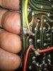
So far I've noticed the left channel is now erratic, the right channel seems same as before the recap. Left channel is open on the meter. What could have happened? Right channel DC offset is ok. Left open. Where to now? I double and triple checked my work, no issues I could see. I did notice a broken terminal post that broke the traces on either side of it. I fixed that, though. The customer now tells me someone else was monkeying around in there. Had I known that, I may not have taken the job. Oh well, I'm in it now.
 
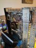
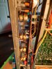
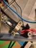
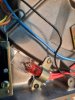
Here are some pics of the adventure. I also included some pics of the neon bulb replacement I did on his Technics turntable. Now it has a green spooky strobe glow. I am now going to take the board out again, I'll get good at this part now. Obviously I must have missed something,
 

Attachments

  • Marantz 2238b diassembled.jpg
    Marantz 2238b diassembled.jpg
    156.2 KB · Views: 25
  • Marantz 2238b diassembled top.jpg
    Marantz 2238b diassembled top.jpg
    120.9 KB · Views: 23
  • PE001.jpg
    PE001.jpg
    163.9 KB · Views: 21
  • PE001-2.jpg
    PE001-2.jpg
    175.4 KB · Views: 21
  • Reassembled.jpg
    Reassembled.jpg
    125.6 KB · Views: 22
  • Broke trace on post.jpg
    Broke trace on post.jpg
    115.1 KB · Views: 21
  • Fisrt power up.jpg
    Fisrt power up.jpg
    112.2 KB · Views: 21
  • Neon after.jpg
    Neon after.jpg
    125 KB · Views: 21
  • Neon before.jpg
    Neon before.jpg
    132.5 KB · Views: 22
Then the moment of truth, I hit the power and the relay kicked in ok, then out, then in again.
Did you power-up the receiver using your Dim Bulb Tester? Was the light glowing or dim when the relay was clicking off?
If you haven't already done so, you should check all of the DC voltages from the Power Supply board to make sure they are OK. Also, you can check/set the Power Supply and Power Amplifier adjustments from the SM.
upload_2022-5-21_8-0-58.png
 
Great info, thanks a bunch. I'll get back to you as soon as I know more. Busy with lots of other customers now, maybe next week. I'm not rushing into it.
 
Hi again,
Sorry about the lag, I left it for a few days and came back to it after I got a good input source. I am using my phone and an adapter to RCA plugs. Magically the all outputs were quite clean, aux, tape monitor, and FM. Turned the amp off, and later it had some intermittent static again, which cleared up some after leaving the amp on for a while.

I thought I may as well finish the recap on the main power board, as I only recapped the ones I could easily reach at first. Now I did them all except for a few under the speaker switch rail that were blocked.

Now when I turned it on, the relay didn't click on, later after checking my work for pins shorted, polarity issues etc.(I checked at least 10 times after I recapped and again now.) I found no errors.
The next day the relay did click on, and I got only some static. Now I'm getting some signal through, but very low volume and crunchy.
The DC voltage at J722 reads 35 V, checked the emitter voltage at Q708 was really wonky, reading anywhere from 130 to 180 DVC and bouncing all over the place. Should I take it out and measure it then? All the other transistor seem ok, testing .5v from emitter to base.
 
Back
Top Bottom