• The move to the new server is done. There are some software and database maintenance updates in process. This has us passing the hat around to help out. We appreciate any donations. Seriously, even a dollar helps. The payment page may be found here - https://www.audiokarma.org/support.html

Marantz 2250

drmazzei

Member
Hello, I'm repairing a 2250 for a friend. My problem is that I'm not getting anywhere near the correct amount of DC to my P800 (J801, J803). I have checked the power supply caps and both have ESR=0.02 as well as capacitance above the rated 10,000 (11,910, 10900). I suspect that the bridge rectifier H007 is the problem. I'm confused about how to test it using a multimeter. Any help would be appreciated.
 
Register to hide this ad
Welcome to AudioKarma!

The P800 power supply board gets power directly from the transformer via the yellow pair (J801 and J802) and the black lead (J803). The bridge rectifier and the big filter capacitors supply power to the main amplifiers only, and get their power from the transformer using the orange wire pair.

Check for AC (not DC) voltage across J801/J802, which should show twice the AC voltage as across J801/J803.

Is there DC voltage across J804/J805? This should be 35VDC.
 
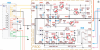
Thanks for checking. Those voltages are much lower than normal. I do not remember what they should be for that model. But notice on the schematic that the collectors of both H801 and H802 should be about 44.5VDC. Here is a high resolution colorized version of the 2250B, which is nearly identical to the 2250.

upload_2022-1-24_19-2-33.png

Next measure resistance across the yellow pair going to J801 and J802. Disconnect one of them from the board jumper before measuring. You are checking to see if the winding on the transformer is open (infinite resistance). I just measured a 2270 transformer and the yellow/yellow pair showed 10 ohms, and yellow/black showed 5.1 ohms.`
 
After I sent you my readings, it dawned on me to rethink what I had modified/replaced on the P800 board. So, I rechecked my work and realized that the solder joints @ J801-J803 might have loosened. After resoldering these points, I rechecked
AC voltages and got J801-2=58.5v and J801-3=35.0v. However, the J804-J805 was still not correct. So I measured the collectors at H801 and H802 (H801=36.8v, H802=0.20v). The reading at the R801/R802 junction is 35.5v and the reading between R803/C803 is 7.6v.
Previously, I have changed electrolytics: C801=330/63, C802=220/50, C804=47/50, C805=680/50, C806=440/35, C807=10/50, C808=47/25, C809=220/35. I also replaced R801 (measured before install at 14ohm). A few transistors replaced: H801 is MJE15032G, H802 is KSC2383YTA, H805 is KSC945.
 
Thanks for the info. A lot of components replaced. Is 680/50 for C805 a typo? And 440/35 for C806?

Per the schematic, the collectors for H801 and H802 are connected to each other. So they should measure the same. I confirmed this on a 2250 power supply. With the power off, test for continuity between the two collectors. If none, then check solder joints.

Some clear pictures of the top and the bottom of the circuit board may prove helpful.
 
Check the solder joints for the collectors for H801 and H802, and the condition of the trace between them including possible lifted pads. Here's a picture showing where:

2250 P800 H801 H802 collectors.JPG
 
Thank you. I'll check the continuity and the soldering. The C805 filtering cap is UPW 680/50 and C806 is UPW 470/35. The picture is very helpful.
 
Continuity for H801 and H802 good. J801-J802=58.6 v AC, J801-J803=29.72 v AC. Both H801 and H802 collectors around 36.5 v DC (schematic states 45.5 v). However, H802 E=7.18 v, B=2.95 v. H801 E=1.99 v, B=2.51 v. H803 collector is 2.54 v. Junction point between. R804 and J804 is 1.99 v as opposed to 35 v. Checked R802 and R803 and both measure 4.7K resistance. Something is still not good and I'm not sure how to proceed.
 
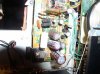
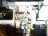
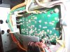
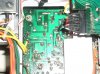
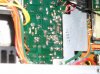
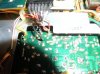
I set down this project for a few days to collect my thoughts. Further measurements R801 is around 36v both in and out. H808 is 27.0v in and 27.5 v out. H811 is 26.5v in and 26.0v out. Attached are photos. I rechecked continuity and everything seems to be ok. I am still puzzled as to why the collector values are low going to H801 and H802.P1010146.JPG P1010147.JPG P1010148.JPG P1010152.JPG P1010153.JPG P1010156.JPG P1010157.JPG P1010158.JPG P1010151.JPG P1010152.JPG
 

Attachments

  • P1010155.JPG
    P1010155.JPG
    149.5 KB · Views: 22
Back
Top Bottom