• The move to the new server is done. There are some software and database maintenance updates in process. This has us passing the hat around to help out. We appreciate any donations. Seriously, even a dollar helps. The payment page may be found here - https://www.audiokarma.org/support.html

Marantz 2252 balance potentiometer wiring.

Dawid Ratal

New Member
Hello Group,

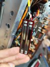
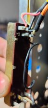
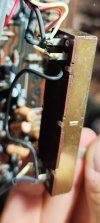
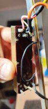
I have a problem with the correct connection of the Marantz 2252 balance potentiometer. Would someone be kind enough to mark in the photo how to connect it exactly? I tried according to the diagram, but it doesn't work properly. So I don't know where I'm going wrong.

I will be grateful for your help.


Marantz potetntiometer schem.jpgMarantz potetntiometer.jpgMarantz potetntiometer 2.jpg
 
Register to hide this ad
I think your schematic (above) has an error in it (see comparison with Marantz SM below).
Your schematic is missing the ground connection on both sides of the slider.
My numbering is random, there could be some numbers on the part itself.

1708019369787.png
Looking at your part, it looks something like this:
The two outer tabs are the resistor and the inner ones connect to the slider.
I don't know the orientation for your receiver. Hopefully, your wire lengths will determine that. Also, don't know which slider is L & R, determine this from your wiring to the amp.
Hope this helps!
Maybe someone else with a 2252 can take a photo of the wire colors to the balance control.
1708019481110.png
 
Unfortunately this solution doesn't work. The sound comes through but the balance doesn't work properly, it makes it louder or louder. I tried various arrangements - nothing worked....
 
The sound comes through but the balance doesn't work properly, it makes it louder or louder.
Why don't you test the control with your ohm meter first? My guess is that you re-installed the slider backwards.
  • First measure the resistance from terminal 1 to 2 (on my annotated photo post #2). It should read 500K ohms.
  • Then measure the resistance from 1 to 3, it should measure from about 0 ohms to about 500K ohms as you slide the slider.
  • If not, then you have the slider installed backwards, otherwise go to the next step.
  • Next, measure the resistance from terminal 4 to 5, again it should read 500K ohms.
  • Then measure the resistance from terminal 5 to 6, and it should measure from 0 to 500 ohms as you move the slider in the opposite direction as your first measurements.
  • If it doesn't do this, then you probably put it back together wrong.
  • You don't show it on your photos, but the wiper arm only goes in one direction. I believe the taller arm should be positioned to contact the silver trace and the short arm. Look at the wear marks on the silver and carbon where the slider fingers have worn the metal and carbon. The silver has one line while the carbon has two lines. If not, then you put it together backwards.
  • Please check because I can't tell exactly from my photo.
Show me a photo of how you mounted the slider onto the bottom of the control.
It should look similar to this one in my photo below.
One set of contacts sits deeper than the other set and have only one contact. This should contact the silver metal strip.
The double contacts should slide on the carbon.
If you installed it backwards, it might not be making contact or shorting between contacts.

1708063146909.png
 
Last edited:
Why don't you test the control with your ohm meter first? My guess is that you re-installed the slider backwards.
  • First measure the resistance from terminal 1 to 2 (on my annotated photo post #2). It should read 500K ohms.
  • Then measure the resistance from 1 to 3, it should measure from about 0 ohms to about 500K ohms as you slide the slider.
  • If not, then you have the slider installed backwards, otherwise go to the next step.
  • Next, measure the resistance from terminal 4 to 5, again it should read 500K ohms.
  • Then measure the resistance from terminal 5 to 6, and it should measure from 0 to 500 ohms as you move the slider in the opposite direction as your first measurements.
  • If it doesn't do this, then you probably put it back together wrong.
  • You don't show it on your photos, but the wiper arm only goes in one direction. I believe the taller arm should be positioned to contact the silver trace and the short arm. Look at the wear marks on the silver and carbon where the slider fingers have worn the metal and carbon. The silver has one line while the carbon has two lines. If not, then you put it together backwards.
  • Please check because I can't tell exactly from my photo.
Show me a photo of how you mounted the slider onto the bottom of the control.
It should look similar to this one in my photo below.
One set of contacts sits deeper than the other set and have only one contact. This should contact the silver metal strip.
The double contacts should slide on the carbon.
If you installed it backwards, it might not be making contact or shorting between contacts.

View attachment 3120216

Thanks for the answer, of course I did it at the very beginning to verify the paths with an ohmmeter. Everything is as you wrote. The silver and carbon tracks are ok. I managed to get the setting right. Everything works as it should. When I get home I will describe the exact setting because it may be useful to others. I wish you all the best!

Thx!
David
 
Thanks for the answer, of course I did it at the very beginning to verify the paths with an ohmmeter. Everything is as you wrote. The silver and carbon tracks are ok. I managed to get the setting right. Everything works as it should. When I get home I will describe the exact setting because it may be useful to others. I wish you all the best!

Thx!
David
No follow up about your "exact settings?" (I'm having the same balance issue.) Do you have a photo of the final correct wiring you can share?
 
No follow up about your "exact settings?" (I'm having the same balance issue.) Do you have a photo of the final correct wiring you can share?
1000048361.jpg
1000048362.jpg
1000048364.jpg
maybe this will help. Let me know if dosent work. I can find any other photos from the others device I've I taken.
 
Last edited:
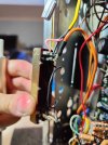
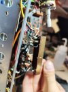
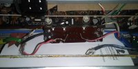
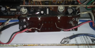
Still struggling with this dang wiring issue...it appears the wiring scheme on my 2226 is a bit different than on your 2252. Mine has three wires coming to each end - red/input, black/ground, white output. The pot. has 4 pins on each end. It seems there needs to be a wire connecting across to each end, but I don't have any idea which posts should be connected.

I've attached a photo this time, hoping someone/anyone may have a pic of a correctly wired slide balance control for a 2226. Any help will be greatly appreciated!
Note: blue wire seen in photo is not part of this.
 

Attachments

  • marantz 2226 balance pot.jpg
    marantz 2226 balance pot.jpg
    73 KB · Views: 6
Some questions so I can better understand where the wires come from and the slider terminal configuration:
  1. Can you post a better lighted photo of only the balance slider so I can clearly see the connector numbers and terminals?
  2. Also, can you tell me where each of the wires come from (probably JHxx)?
  3. How many wires in total were soldered to the slider?
  4. Was there a black wire connecting two terminals, one on each side?
  5. Is that black wire just cut off (hard to tell from the poorly focused photo)?
 
Last edited:
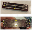
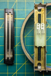
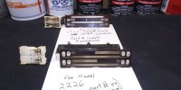
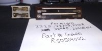
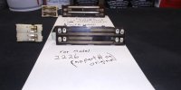
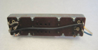
UPDATE: After further exploring, I now see that the replacement balance pot. I purchased is similar and functions, but is not the same as my 2226 original pot. as shown in the photos below. No parts can be swapped and the wiring is different from the 2252.

Current situation:
1. I am still looking for a replacement slide potentiator for a Marantz Model 2226.

2. I have a working balance pot. for a Marantz 2252, et.al. (see photos for applicable to other models)

Maybe these pics can prevent someone else from wasting a bunch of time....(deep sigh.)

20250201_144832.jpg
20250201_144752.jpg20250201_144752 (1).jpg
 
@Mattma--, I have a few more questions for you, then we can solve this issue. Please answer them to proceed.
  1. What was wrong with the original 2226 balance slider that you needed to replace it?
  2. What it just that you couldn't figure out how to re-wire it back in?
  3. Does the new slider mechanically the same size and mounting as the original?
  4. Can you provide pictures of the back (terminal) sides of both your original and new slider? (that looks similar to this photo and readable terminal numbers)?
  5. You said there are 3 wires on each end (red, black, white). Please follow EACH wire and tell me which board AND terminal number it comes from and which terminal on the volume control the other side goes to.
  6. Provide a photo of those wires attached to the volume control.
  7. When you take your photos, you need better lighting to see details clearly. Either take it outside for the photo or add another lamp nearby.
Thanks. ;)

EDIT: Does this help. I found a photo on the internet showing a slider like your original.
Wait a second... is the 1st photo THE ORIGINAL slider? It has 4 tabs on the top and bottom with a larger space in the middle.
But, in the photo above the one labeled 2226 has 3 tabs on each side, spaced equally across the slider.
Which one is the original that you unsolder the wires from?

1738511717576.png

From the internet:
1738511773693.png
 
Last edited:
Here's the whole story:
I purchased this unit last month locally via Ebay, mainly because it's the same model as my very first Marantz from the 1970's. The local pick-up eliminated steep shipping costs, and kept the purchase total below my "deal breaker" limit.

The unit came with a few "surprises":

The next day I was getting ready to look inside and noticed one rear foot was broken and taped back on. No big deal, except the next thing I see is a bent chassis. This unit has been dropped and HARD! Inside I find that someone (not the seller) has been in there ahead of me sometime in the distant past. New style LED lamps (will be switching back to traditional lamps), replacement dial string, plastic lamp section with several cracks (fixed now), and a balance slider circuit board cracked/broken on both ends, as seeable in previous photos. The balance unit has no markings on it whatsoever - no part/capacity numbers and no numbers by the posts.

(A few days later I noticed that the entire lamp function indicator section is missing as well (only the dial lamp section with those X:"+# LEDs).

Not having the correct part number, I gambled and bought the "new" unit on Ebay hoping it would be the one I needed - it is not.

Your 2252 and my 2226 do use the same part -RS05040050. That is not what I purchased, and at this point I am not certain if the unmarked balance pot. that came within this unit is even correct or not.

So, for now I am setting everything aside, while I search/shop for the correct balance pot. And I do have the other one available, if someone needs it --it looks like it fits many other Marantz models, but not the 2226.

Dawid, I thank you once again for your kind assistance, and I apologize for essentially wasting both of our time up until now, and for the poor quality of my photographs. Unfortunately, I suffer from a chronic condition known to many as "Old Man/Techno Syndrome".... and I'm pretty sure at this advanced (st)age, it's incurable!

I did learn a lot along the way during this adventure, so I don't consider it a total loss whatsoever. Also, I have two other Marantz units up and running fine, so it's not like I'm going without music.......

Until the next time,
Mattma
 
The photos of both the old and newly purchased balance sliders look like you should be able to adapt it to your installation... as long as it physically fits into the chassis. But you seem reluctant to provide any of the information that I would need to determine how to wire it in. I do not have a 2226 sitting in front of me, so your photos are all I have to determine how to wire it in.
 
Back
Top Bottom