dave404
New Member
I've been trying to fix a friends 2252b that he got several years ago and I'm having a difficult time figuring out what I could have done to FUBAR it. Hoping the large brains here have an answer.
As some backgroud I'm not new to this. I've fixed several Marantz and Pioneers in the past but I'm not immune to stupid mistakes.
When I first tested the unit one channel was dead. One of the output transistors was shot. There wasn't any physical reason that I could see as to why that would happen: no burnt resistors or such which is what I've seen when that happens.
The other channel had clipping. Taking out the output transistors and checking them verified they were good and were put back in.
At the time, the voltages on the transistors were not correct, according to the schematic. I wish I had written them down but I didn't.
So at that time I was thinking ok.. I know the first channel is good, I'll start swapping transistors from good to bad to see if I can pin it down.
I started at the input and worked my way up through Q707-710. Here's where I made the mistake: I switched the two transistors putting Q710 in Q709 spot and Q708 in Q707 spot. No, I didn't have a DBT. Instant smoke on R737 and R739. Lesson learned.
And I also burned up transistors in the Q709 and Q707 spot.
I replaced the resistors and the transistors with MJE253G and MJE243G, which I believe I got from somewhere on the forum. I replaced all 4 in the interest of keeping everything as even as possible.
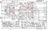
Here's where the problem comes in. I now have very strange voltages and I cannot pinpoint what the problem is. The voltages are on BOTH channels and are consistent. Vb Q701 and Q702 are correct as is Ve Q701 and Q702. Vc on them is a little high at -42.2v.
On Q705 and Q706, Vc is 4.8v, Vb is -42.2v and Ve is -42.5v. These should be -1.1v and around -40v.
Q716 and Q718 is Ve 3.7v, Vb approx 3.6 on both and Vc 3.7v. On Q715 Vb is 3.5v, Ve is 3.8v and Vc is 3.8v. For Q717 Ve an Vb is 0v and Vc is 3.8v.
Q707 and Q709 are Vc +42.5v and -42.5v respectively, Vb is 4.7v on both and Ve is 4.1v and 3.8v respectively. Q708 and Q710 have similar readings.
First question: was the replacement for Q707-710 correct? Any thoughts?
Second, I'm contemplating putting two good originals of the 707-710's back in and see what that does?
Or am I missing something obvious? I have poked around the board and have removed and out of circuit tested the blob diodes and they seem to be good.
Any help here would be great.
Cheers
As some backgroud I'm not new to this. I've fixed several Marantz and Pioneers in the past but I'm not immune to stupid mistakes.
When I first tested the unit one channel was dead. One of the output transistors was shot. There wasn't any physical reason that I could see as to why that would happen: no burnt resistors or such which is what I've seen when that happens.
The other channel had clipping. Taking out the output transistors and checking them verified they were good and were put back in.
At the time, the voltages on the transistors were not correct, according to the schematic. I wish I had written them down but I didn't.
So at that time I was thinking ok.. I know the first channel is good, I'll start swapping transistors from good to bad to see if I can pin it down.
I started at the input and worked my way up through Q707-710. Here's where I made the mistake: I switched the two transistors putting Q710 in Q709 spot and Q708 in Q707 spot. No, I didn't have a DBT. Instant smoke on R737 and R739. Lesson learned.
And I also burned up transistors in the Q709 and Q707 spot.
I replaced the resistors and the transistors with MJE253G and MJE243G, which I believe I got from somewhere on the forum. I replaced all 4 in the interest of keeping everything as even as possible.
Here's where the problem comes in. I now have very strange voltages and I cannot pinpoint what the problem is. The voltages are on BOTH channels and are consistent. Vb Q701 and Q702 are correct as is Ve Q701 and Q702. Vc on them is a little high at -42.2v.
On Q705 and Q706, Vc is 4.8v, Vb is -42.2v and Ve is -42.5v. These should be -1.1v and around -40v.
Q716 and Q718 is Ve 3.7v, Vb approx 3.6 on both and Vc 3.7v. On Q715 Vb is 3.5v, Ve is 3.8v and Vc is 3.8v. For Q717 Ve an Vb is 0v and Vc is 3.8v.
Q707 and Q709 are Vc +42.5v and -42.5v respectively, Vb is 4.7v on both and Ve is 4.1v and 3.8v respectively. Q708 and Q710 have similar readings.
First question: was the replacement for Q707-710 correct? Any thoughts?
Second, I'm contemplating putting two good originals of the 707-710's back in and see what that does?
Or am I missing something obvious? I have poked around the board and have removed and out of circuit tested the blob diodes and they seem to be good.
Any help here would be great.
Cheers