


MBuras
Restoration is an Addiction
I was recently working on a Marantz 2270 that is very late production, from October 4th, 1975. Serial number is #U462378. We all know there were a few service bulletins issued on this model but I've never seen pics of the mods.
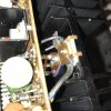
First up is service bulletin one which changes the temperature compensating transistor from the round 2SC984 to a flat 2SC496. Here is a picture of the factory custom bracket to mount the new transistor and include the bias diode alongside.
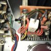
And next up isn't a service bulletin, at least that I'm aware of, but is a common good practice on some of these older units. Many of them didn't come with flyback diodes from the factory. This late production model did have flybacks installed and best I can tell they were either factory or early service center work.
They were installed as follows to each amp board:
cathode to J753, anode to J754. cathode to J760, anode to J761.
First up is service bulletin one which changes the temperature compensating transistor from the round 2SC984 to a flat 2SC496. Here is a picture of the factory custom bracket to mount the new transistor and include the bias diode alongside.
And next up isn't a service bulletin, at least that I'm aware of, but is a common good practice on some of these older units. Many of them didn't come with flyback diodes from the factory. This late production model did have flybacks installed and best I can tell they were either factory or early service center work.
They were installed as follows to each amp board:
cathode to J753, anode to J754. cathode to J760, anode to J761.


