• The move to the new server is done. There are some software and database maintenance updates in process. This has us passing the hat around to help out. We appreciate any donations. Seriously, even a dollar helps. The payment page may be found here - https://www.audiokarma.org/support.html
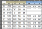
Here's what I gather from your transistor substitutions:
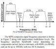
I think that the frequency should be OK, since the MPX frequency is < 100kHz.
1707884961205.png
But your hFE (gain) could be lower/higher than the original transistor, which could affect the gain stages if your parts are on the lower end.

1707884763662.png
Did you replace H304, H305, H306, H307 also? What did you use?

Also, the SM says:
1707885879342.png
Do you have an oscilloscope or Freq Counter or DMM that can measure 19kHz to check for signal?
You can also check DCV on each pin of H321 against the schematic.
1707886088411.png
 
Last edited:
Do you have an oscilloscope or Freq Counter or DMM that can measure 19kHz to check for signal?
You can also check DCV on each pin of H321 against the schematic.
No scope and no meter with frequency counter. For the heck of it, I tried to read the frequency on my good 2275 with a hand held meter and it wouldn't read, but with a pure tone it would at 19kHz. I believe there was an AC voltage at that pin that looked about right so I also suspected that the frequency is too far off that the pot can't be adjusted enough.

I believe as well that the voltages are all okay looking. I suggested a look at the other 19k Osc components - check the resistor and stick in a new cap. I don't know if that happened or not?
 
Here's what I gather from your transistor substitutions:
I think that the frequency should be OK, since the MPX frequency is < 100kHz.
But your hFE (gain) could be lower/higher than the original transistor, which could affect the gain stages if your parts are on the lower end.
Did you replace H304, H305, H306, H307 also? What did you use?
Do you have an oscilloscope or Freq Counter or DMM that can measure 19kHz to check for signal?
You can also check DCV on each pin of H321 against the schematic.

Dankik:
- the hFE values on my 2SC1815s were all around 220-230
- I did NOT replace H304, H305, H306, H307 (I only replaced the 2SC2828S transistors: H302, H303, H308, H309, H310, H311, H313, H314, H315, H316, H317)
- I do NOT have a scope, frequency counter, or multimeter with freq capability
- I already checked all pin voltages on the H321 chip, please see my post #3 above
 
I believe as well that the voltages are all okay looking. I suggested a look at the other 19k Osc components - check the resistor and stick in a new cap. I don't know if that happened or not?

which specific components should I be checking that will affect the 19kHz?... are they only on the P300 MPX board?
 
rBuckner: in posts #38/39, you said:

I guess you're left with testing the parts that are in the 19kHz circuit off of the IC. I think that would be the pot of course, R311, R312 (16K) and the cap C305 (470pF).
The cap C305 appears to be a polystyrene. Great caps unless they get damaged. They don't take heat well. If you can't test it, I'd suggest trying to order one but may be hard to find new - I wouldn't trust old ones. You could get a C0G dielectric one or better. NPO is next best type.
One other observance, you used film caps for the 3 bipolars next to the IC. I have heard that sometimes this doesn't work but don't recall what the failure mode was. You might try putting the old caps back in. Two of them are to do with "19kHz loop filter" and the other is "Stereo switch filter". Hmmm... maybe this is the issue?

R311 potentiometer: I measured this in circuit, and witnessed the resistance vary from 0 - 4.8K (across a couple of the leads), so I assume it's functioning properly since it's a 5K pot... also cleaned the pot

R312 resistor (16K): I measured this in circuit as 16K, seems OK

C305 cap (470pF): not sure how to check/measure this one???... my meter's lowest range is 20nF, which is probably far too coarse? (readout resolution is 2 digits after decimal).. ***TBD***

Use of film caps instead of e-bipolar: this guy used film caps in those 3 positions, with apparently OK results... I think my Panasonic films must be similar?... see his (great) pics and description of a P300 board rebuild HERE
 
Those film caps had to have worked as you've been running it for some time. I wasn't thinking of that right then!

On the cap, 470pF equates to 0.47nF. It should read something. There will be stray capacitance from the leads so what I do is get positioned, check the reading, measure a small value cap and subtract that stray cap value. Say it reads 0.13nF with no cap on the leads. A perfect 470pF should read 0.60nF then. Limited of course by the meter's accuracy.
 
I'm just going to replace cap C305 with a new one (might as well if I have to de-solder regardless just to measure it)

also, I'm not ruling out a defective C305, but my gut is starting to tell me that my problem might be stemming from an incorrect adjustment (somewhere on boards P100, P200, P300), rather than a bad component... don't have much to lose by tweaking some of these (can't be much worse than the tech who recently broke 3 adjusters while "fixing" my issue, ha ha)

just ordered the plastic tool alignment kit (Aven 13016), plus a 470pF ceramic cap for C305
 
Capacitor C305:
I replaced with a new one... NO DIFFERENCE... also tried adjusting the R311 pot, but as usual this strangely had NO DISCERNIBLE EFFECT, and did not activate stereo, despite trying full rotation each way (note: the original cap I pulled seemed to measure OK, so it was probably OK)

Discriminator:
I tried adjusting the discriminator coil on the FM IF P200 board... used my new Aven-brand plastic adjusting tools!

#1) by turning the UPPER coil, I was able to set the Center tuning meter and it seems to work correctly... this was achieved within about 5-10 degrees of rotation, the hex core was not stuck, and I could feel it rotating smoothly with some resistance (note: this coil is reached from the top side of the receiver, through an access hole in the FM-Dolby board labelled "FM-IFT2" on the cosmetic metal cover... the P200 board is mounted on the underside of the chassis, however, it's mounted *upside down*, so the components in fact point "to the sky", same as all other circuit boards)

#2) by turning the LOWER coil... it seems to have NO DISCERNIBLE EFFECT on my sound or signal quality (either meter), even with a fair bit of rotation each way (1-2 turns?)... this was surprising, since I thought this was a "delicate" adjustment... ???... the hex core was not stuck, and I could feel it rotating smoothly with some resistance (note: this coil is reached from the bottom side of the receiver, through an un-labelled access hole in the silver metal cover plate for P200)

FM Oscillator:
I tuned to my strongest station (99.9), then on the FM Front End board P100, I adjusted the two adjusters labelled "FM-OSC"... I rotated both the LARGE one on the right side (has a metal hex barrel), and, the TINY one on the left side below the tuning capacitor (has a tiny metal flat-head)

to adjust, I used my ears mainly, plus the meters, and tried a fair bit of rotation on each until I discovered what "the zone" was for good reception, then tweaked them to optimize... the sound seems generally better now (clearer and stronger), plus I was able to correct an inaccurate dial pointer!... now, 99.9 comes in at 99.9 (not at 99.0 like before)... also, it seems that my Signal Strength meter works better now: before, it never seemed to drop down to zero when it should, now it does (while still going up high on strong stations)

so, pretty decent mono FM now, but sadly, STILL NO STEREO! :-(
 
Last edited:
I've been out of commission for a bit (COVID, etc.), trying to get back on this between tax returns!

fwiw, I received this comment on YouTube from Dave Sanders, which I think is valuable info:

"The MPX board (P300) has the Stereo Decoder IC (H321) which is equivalent to the Hitachi HA1156 IC. The internal 76Khz (free-running oscillator) is controlled by an external timing network consisting of C305 and resistors R312 & R311 which are connected to pin14 of H321. You should be able to connect a frequency counter to TP J310 which is the output of the divided down frequency of 76Khz divided by 4 or 19Khz. Adjust R311 to obtain a reading of 19Khz. When the receiver is tuned to an FM Stereo signal (19khz pilot signal present) the FM MPX circuit will detect the pilot subcarrier and through the action of the phase detector (in H321) it will phase lock the free-running oscillator to run at exactly the correct frequency. At this point the phase comparator will send a signal to the lamp driver circuit and in turn will illuminate the “Stereo Indicator” lamp. The reason you are seeing very little effect when adjusting R311(5K pot) is that there is a fixed resistor with a value of 16K ohms in series with it. Therefore, the minimum value is 16K and the maximum value is 21k. This range of values should still allow the circuit to be adjusted to the required 19Khz. If the free running frequency is too far removed from the required value it’s possible that the circuit will never achieve phase lock and the “Stereo” lamp will never come on."
 
Yes - advised this back in post #38:
I guess you're left with testing the parts that are in the 19kHz circuit off of the IC. I think that would be the pot of course, R311, R312 (16K) and the cap C305 (470pF).
It's hard to adjust the 19kHz even with a counter without an FM stereo signal gen in which you can turn off the pilot 19kHz, such as a Sencore SG-165. If you're lucky, there's a strong FM station near you that doesn't broadcast in stereo. We have one here, so it does happen!

Most importantly I hope you've recovered from Covid! I still have some loss of smell/taste after many months!
 
I've been out of commission for a bit (COVID, etc.), trying to get back on this between tax returns!

fwiw, I received this comment on YouTube from Dave Sanders, which I think is valuable info:

"The MPX board (P300) has the Stereo Decoder IC (H321) which is equivalent to the Hitachi HA1156 IC. The internal 76Khz (free-running oscillator) is controlled by an external timing network consisting of C305 and resistors R312 & R311 which are connected to pin14 of H321. You should be able to connect a frequency counter to TP J310 which is the output of the divided down frequency of 76Khz divided by 4 or 19Khz. Adjust R311 to obtain a reading of 19Khz. When the receiver is tuned to an FM Stereo signal (19khz pilot signal present) the FM MPX circuit will detect the pilot subcarrier and through the action of the phase detector (in H321) it will phase lock the free-running oscillator to run at exactly the correct frequency. At this point the phase comparator will send a signal to the lamp driver circuit and in turn will illuminate the “Stereo Indicator” lamp. The reason you are seeing very little effect when adjusting R311(5K pot) is that there is a fixed resistor with a value of 16K ohms in series with it. Therefore, the minimum value is 16K and the maximum value is 21k. This range of values should still allow the circuit to be adjusted to the required 19Khz. If the free running frequency is too far removed from the required value it’s possible that the circuit will never achieve phase lock and the “Stereo” lamp will never come on."
I have not read every paragraph in this most technical thread, but was wondering if you have an external FM antenna installed, or if it is a built in on the power wire? Out in the garage playing with the STA78 (TERRIBLE reception there for any receiver- EXCEPT this one!) with a built in antenna on the power cord, I totally lost the FM stereo lamp on all stations I knew were broadcast in stereo and it upset me greatly. Tried everything to bring it back. No go. When I unraveled the left side speaker wire from the power cord, which were kind of twisted around each other, the reception came in nearly perfect and stereo light hits now on all stations (except ESPN mono broadcast), even weak stations. I can kill the stereo lamp merely by lifting up the speaker wire OR power cord and moving it 2 feet in the air in either direction on any station. Found a sweet spot where power cord and speaker wires converge and works and sounds amazing with stereo lamp hitting solid every time! I'm sure this is probably NOT the technical issues you're experiencing, but something to ponder, perhaps. Feel free to have moderators erase this post if it sounds ridiculous...
 
Stayjoy78: thanks for the suggestion... but that's not my issue, because I'm using an external antenna (basic T-dipole), my speaker wires are fine, plus my 2230 receiver works fine for FM stereo reception in the same physical location... thanks anyway!
 
Last edited:
*** FIXED !!!!! ***

I finally was able to find a decent tech who fixed this receiver... turns out that the FM Front End board was significantly contaminated, which due to the very sensitive nature of that board, threw everything out of whack and did crazy things, all of which was transmitted downstream to the other FM boards

he found weird white gunk residue hiding under the tuning capacitor (possibly some sort of lube?), that had spread to other parts of the board (my recent attempt to clean the tuning cap with non-residue cleaner might even have helped spread the residue)... the only way to fix it was to pull the entire module and strip and rebuild the entire PCB board, while removing every trace of residue... the residue was no overtly visible to the naked eye, certainly not the stuff under (and probably inside) the tuning cap

after that, it all came down to standard alignments and adjustments throughout all the FM boards

I don't think that any components were actually replaced with new ones, so my part replacements were largely a waste of time

she runs great now: FM is very sensitive, selective, and the STEREO light comes on!

HUGE thanks to all of you who posted and helped me along this journey, hopefully this discussion can help out someone else

:)
 
Last edited:
Well, it didn't measure it. Probably the audio riding on it messed it up. I used a signal generator and it read fine up to 19kHz. Dang!!

I guess you're left with testing the parts that are in the 19kHz circuit off of the IC. I think that would be the pot of course, R311, R312 (16K) and the cap C305 (470pF).
Just an FYI for future readers, my FLUKE 117 meter (in AC/Hz mode) was able to read the 19kHz frequency on J310 to J312 (ground). Of course, these are not cheap meters but wanted to add this note to your thread.
 
having a problem with my Marantz 2275 receiver.....

DESCRIPTION
- FM not in stereo: receives stations well enough, but they're playing in mono, and the stereo lamp does not light up
- *however*, in a few tiny spots on the dial, I can sometimes get a shred of stereo, but extremely poor quality (noisy, unstable, weak, hard to tune)... but it's in stereo, and the stereo lamp lights up!

INFO
- the Muting function works properly, and does NOT kill the sound when activated
- the Muting Level level pot (on backside) works as it should to control muting strength... I've set it to minimum
- the stereo lamp itself is OK: it lights up in Aux/Phono/Tape, plus, works fine in the case of "shred of stereo" (described above)... lamp is a low-current LED
- confirmed: Muting button is off, Mono buttons are off
- confirmed: I'm definitely hearing mono, not stereo
- meters: both signal strength & center meters appear to work normally... signal strength approx. 75% on strong stations
- using a dipole T-antenna
- receiver was fully recapped 7 years ago

THINGS I'VE TRIED
- replaced H321 (multiplex decoder chip) with a new HA1156... no difference, put original back in
- replaced all 2SC2828S transistors with new 2SC1815s (includes: H302, H303, H308, H309, H310, H311, H313, H314, H315, H316, H317)... no difference
- Antenna / Muting Level board: removed & checked integrity, cleaned the 2 pots... no difference
- visually inspected all electrolytic caps on P300 board (all caps were replaced 7 years ago with Panasonic FC, plus some films)... all looked OK

ABNORMALITIES?
- adjusting R311 seems to have very little to zero effect... this seems surprising, and might offer a clue?... accordingly, it can't be adjusted to successfully activate stereo
- *however*, when I can get a "shred of stereo", adjusting R311 does seem to do something, and I can make stereo go on/off (within approx. 20 degrees of rotation)... the effect is minor, but it's there
- note: R311 is the MPX-OSC pot that tweaks the 19kHz signal

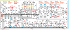
schematic for the P300 Multiplex board posted below

my voltage readings from the MPX Decoder chip (H321) posted below

looks like the "no stereo FM" problem is not uncommon, however my situation seems different in that the muting function does not kill the sound and seems to work properly

any help GREATLY appreciated!

 
Did you clean out the Tuning Cap with non-residue cleaner and air? If you don’t use FM or tune FM often maybe there’s buildup.
 
Back
Top Bottom