


I read a number of threads about bias issues with the P700 amp boards in the Marantz 2275 and in other Marantz units. A lot of great information freely shared by other members. I came away not completely clear on the best approach to restoring the P700 board and thought I would start another thread on the subject.
I just restored a 2275 P700 board and replaced all the transistors and some of the diodes on the board including the output transistors. I replaced H713 and H714 with MJE15032G and MJE15033G transistors and I could only bias the board down to 20MV at the range limit of the adjustment pot R742. The 2275 parts list states R742 is a 1K pot but the unit installed was a 2K pot. Installing a 1K put only makes matters worse bias-wise. I am assuming somewhere along the way there were engineering changes made to the P700 board that account for the change in the R742 value.
What I did to allow the bias to be set properly was replace the jumper R743 with a 1.8K resistor using the 1K R742 bias pot I had installed per the parts list. With this combination, I was able to dial in the bias to 10MV per the service manual. A more elegant approach I guess would be to use a 3K pot for R742 and leave the R743 jumper in place .In another thread I read that using KSC2073TU and KSA940TU for H713/H714 instead of MJE15032G and MJE15033G that I used would also solve this issue. I also observed that the bias transistor H709 is installed under H713 on the P700's I have worked on VS. the location shown in the service manual and on the P700 I am currently working on.
Another variation is that on some P700 boards H710 is tucked under the H713 heatsink while on others it is just sticking up from the board. Not sure which is the proper location for it and why there is a variation in the position. H710 is in series with the bias pot R742 so it's operating temperature directly affects the bias setting. Tucking it under the H713 heat sink next to the bias transistor H709 makes sense to me but wondering why the location varies. Another thread recommends replacing H710 with two 1N4148 diodes in series, which would eliminate the thermal compensation that the original thermistor provided.
The service manual does not indicate if you should allow the 2275 to warm up before setting the bias, which is interesting in that operating temperature will clearly affect the bias setting with the original H710 installed. A lot of variations to consider, hoping others have suggestions on the best course of action to take with refurbishing the 2275 P700 board.
Sorry for being a bit long-winded, I will try to summarize:
1. What is the best approach to positioning/replacing H710?
2. When replacing the Bias pot what is the best value to use?
3. What transistor pair to use for H713/H714?
4. Any other suggestions…….
Thanks everyone for listening!
Rich
I just restored a 2275 P700 board and replaced all the transistors and some of the diodes on the board including the output transistors. I replaced H713 and H714 with MJE15032G and MJE15033G transistors and I could only bias the board down to 20MV at the range limit of the adjustment pot R742. The 2275 parts list states R742 is a 1K pot but the unit installed was a 2K pot. Installing a 1K put only makes matters worse bias-wise. I am assuming somewhere along the way there were engineering changes made to the P700 board that account for the change in the R742 value.
What I did to allow the bias to be set properly was replace the jumper R743 with a 1.8K resistor using the 1K R742 bias pot I had installed per the parts list. With this combination, I was able to dial in the bias to 10MV per the service manual. A more elegant approach I guess would be to use a 3K pot for R742 and leave the R743 jumper in place .In another thread I read that using KSC2073TU and KSA940TU for H713/H714 instead of MJE15032G and MJE15033G that I used would also solve this issue. I also observed that the bias transistor H709 is installed under H713 on the P700's I have worked on VS. the location shown in the service manual and on the P700 I am currently working on.
Another variation is that on some P700 boards H710 is tucked under the H713 heatsink while on others it is just sticking up from the board. Not sure which is the proper location for it and why there is a variation in the position. H710 is in series with the bias pot R742 so it's operating temperature directly affects the bias setting. Tucking it under the H713 heat sink next to the bias transistor H709 makes sense to me but wondering why the location varies. Another thread recommends replacing H710 with two 1N4148 diodes in series, which would eliminate the thermal compensation that the original thermistor provided.
The service manual does not indicate if you should allow the 2275 to warm up before setting the bias, which is interesting in that operating temperature will clearly affect the bias setting with the original H710 installed. A lot of variations to consider, hoping others have suggestions on the best course of action to take with refurbishing the 2275 P700 board.
Sorry for being a bit long-winded, I will try to summarize:
1. What is the best approach to positioning/replacing H710?
2. When replacing the Bias pot what is the best value to use?
3. What transistor pair to use for H713/H714?
4. Any other suggestions…….
Thanks everyone for listening!
Rich

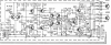
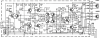

 It might provide some useful information.
