
• The move to the new server is done. There are some software and database maintenance updates in process. This has us passing the hat around to help out. We appreciate any donations. Seriously, even a dollar helps. The payment page may be found here - https://www.audiokarma.org/support.html

Marantz 2275

MikeGarofalo

New Member
Hello,

New member and first time posting.
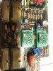
Looking for guidance on easy way to test whether pre-amp circuit on the PE-01 tone board is functioning correctly. There is no sound from either channel and this is the only board that has been worked on (other than power supply,, which has been re-capped and tested. Prior to rework, the receive worked perfectly. Pictured is the board I'm working with. There are no noticeable issues (backward caps, cold solder joints, etc.).

Thanks much!
 

Attachments

  • IMG_2377.JPG
    IMG_2377.JPG
    131.9 KB · Views: 14
Register to hide this ad
Use patch cord from Pre-Out RCA jacks on back to another amp input. Assuming the 2275 has PreOut/Main In jacks.
If not, could use an oscilloscope at the output points on the board. No scope? Can make a signal tracer with a small speaker and a wire with a small cap in line to probe the signal path. Can search around in DIY for build instructions.
 
Use patch cord from Pre-Out RCA jacks on back to another amp input. Assuming the 2275 has PreOut/Main In jacks.
If not, could use an oscilloscope at the output points on the board. No scope? Can make a signal tracer with a small speaker and a wire with a small cap in line to probe the signal path. Can search around in DIY for build instructions.
Thanks.
I'll try to dig up a scope and do some probing.
 
I see a number of threads about this model or similar over in the Marantz Audio forum that might help. Welcome to AK!
 
Make sure the SparkOs modules are in correctly, there's a lot of parts removed/changed with that where things could go wrong. Make sure it's getting power.
 
Make sure the SparkOs modules are in correctly, there's a lot of parts removed/changed with that where things could go wrong. Make sure it's getting power.
Yeah, checked and double checked and looks to be installed per the instructions. PS voltage steady at 35V, but I should measure at the input to the board to be sure it's getting there. Thanks for the reply. Great forum with lot's of people willing to help!
 
Yeah, checked and double checked and looks to be installed per the instructions. PS voltage steady at 35V, but I should measure at the input to the board to be sure it's getting there. Thanks for the reply. Great forum with lot's of people willing to help!
Problem solved. Helps to put the capacitors where they're supposed to go. The label for CE13 cap on the PE-01 board is off to the side, making it difficult to determine where the replacement cap goes. Luckily I took plenty of pictures prior to pulling parts off.
 
Problem solved. Helps to put the capacitors where they're supposed to go. The label for CE13 cap on the PE-01 board is off to the side, making it difficult to determine where the replacement cap goes. Luckily I took plenty of pictures prior to pulling parts off.

That's why I always replace capacitors one by one, removing one capacitor and fitting the new one at the same operation.
 
That's why I always replace capacitors one by one, removing one capacitor and fitting the new one at the same operation.
Yes, for sure. Live and learn I suppose, although it provided not only a lesson learned but a chance to study the pre-amp circuit a bit more than I would have otherwise. On to left channel amp and I'm done!
 
Back
Top Bottom