• The move to the new server is done. There are some software and database maintenance updates in process. This has us passing the hat around to help out. We appreciate any donations. Seriously, even a dollar helps. The payment page may be found here - https://www.audiokarma.org/support.html

Marantz 2325 No Headphones and No Speaker Terminal Output but Relay Clicks?

richardg0n

Active Member
Hi Guys,
I am working on a 2325 restoration, and I can't figure out why the speaker terminals have no output, nor do the headphones. With a DBT connected the protection relay clicks two seconds after powering up. I am using my signal tracer to follow a 1k tone running through AUX and can trace the 1k tone through the PRE(PE01) terminal contacts 7&8 and 13&14 into the Tone Board(PU01). The tone stops just before reaching the headphone jack at JU17 and JU18. At PU01 I do have tone signal, JU06, and JU07 to the PRE/MAIN outs in the back. Selecting the Main and Remote speaker switches has no effect, nor do the other switches on PU01. All switches on PU01 and tape monitors have been deOxited.

The following boards have been recapped. Power Supply P800, Amps P700, Pre PE01, Tone Board PU01, Phono P400, Main Filter Caps replaced.
 
Register to hide this ad
Here are some things to try:
  1. Use your signal tracer to look for a tone at the Main Amp inputs, J701 (center conductor).
  2. If you don't get a signal, then try to install RCA cables to connect the Pre-out to Main In, maybe the internal jumpers are bad.
  3. Make sure that you have +/- 60V going to J017.
 
Here are some things to try:
  1. Use your signal tracer to look for a tone at the Main Amp inputs, J701 (center conductor).
  2. If you don't get a signal, then try to install RCA cables to connect the Pre-out to Main In, maybe the internal jumpers are bad.
  3. Make sure that you have +/- 60V going to J017.
  1. Use your signal tracer to look for a tone at the Main Amp inputs, J701 (center conductor).
    Using the signal tracer, I am getting a tone on center conductor J701 in both amps.

  2. If you don't get a signal, then try to install RCA cables to connect the Pre-out to Main In, maybe the internal jumpers are bad.
  3. Make sure that you have +/- 60V going to J017.
    No voltage on JU17. Looks like the voltage should be coming from pin JU12 on PU01. I followed it back to PS P800 pin J809 and there are no voltage readings. I checked the voltage readings on P800. See attached.
 

Attachments

Last edited:
Make sure that you have +/- 60V going to J017.
No voltage on JU17. Looks like the voltage should be coming from pin JU12 on PU01. I followed it back to PS P800 pin J809 and there are no voltage readings. I checked the voltage readings on P800. See attached.
Not JU17, J017 which is the plug that goes into J710 on the P700 board. You can also measure it on J710 if you can get to it.
J801 & J802 should be AC voltage coming from the transformer. You need to switch your DMM to ACV.

I'm trying to determine if you have both signal and power going into the Main Amp boards (P700). The output of the P700 drives both the speaker and headphone outputs.
  • Your 1st test verified that signal is getting to the input connector on P700 (J701).
  • Next, I wanted to verify that the +/- 60vdc power is getting to the board.

1709151333420.png
 
Last edited:
Not JU17, J017 which is the plug that goes into J710 on the P700 board. You can also measure it on J710 if you can get to it.
View attachment 3133026
Here are the voltage readings for J017
Left:
-56VDC
0VDC
56VDC
726 57VDC
727 -57VDC

Right
-63VDC
0VDC
-63VDC
726 -5VDC
727 0VDC

Looks like I need to fix a separate issue on the right amp. I disconnected the right amp, and the headphones still have no output.
 
Right
-63VDC
0VDC
-63VDC
726 -5VDC
727 0VDC
Both pins are -63v and -5v & 0v?? Try to unplug the connector and measure again on the connector side to see if it is still the same or caused by the P700 board.
Check the voltages on the main filter caps here:
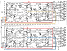
Did you recap these two 15,000uF caps? If you did, check the polarity of the caps... the (+) of C009 is connected to the (-) of C008. There should be a bus bar or wire connecting them also the chassis ground. Since the other main amp board is OK, I think the caps are OK, but check to make sure.
1709155567181.png
 
Last edited:
Both pins are -63v and -5v & 0v?? Try to unplug the connector and measure again on the connector side to see if it is still the same or caused by the P700 board.
Check the voltages on the main filter caps here:
Did you recap these two 15,000uF caps? If you did, check the polarity of the caps... the (+) of C009 is connected to the (-) of C008. There should be a bus bar or wire connecting them also the chassis ground. Since the other main amp board is OK, I think the caps are OK, but check to make sure.
View attachment 3133072

I retook the measurements from the back of J710, where it's soldered to the board.

Left amp
Red 51VDC
Black 0VDC
White 21VDC
Yellow 50VDC
726 58VDC
727 22VDC
IMG_8EB6D4FE3DCD-1.jpeg

Right amp
Red 52VDC
Black 0VDC
White -52VDC
Blue -0.3VDC
726 59VDC
727 4.6VDC
IMG_0511AE3BE651-1.jpeg

Main Filter Caps

White -59VDC is connected to the negative side filter cap.
Red 59VDC is connected to the positive side filter cap.
IMG_D5144E831879-1.jpeg
 
What's changed between earlier and now?
Voltages out of the main caps looks OK, +/-59v.
Did you do any work on the P700 boards, or are they stock?
Can you please pull off the 4-pin molex connector and measure the voltages on the connector (red/blk/wht/yel or blu) for both sides?
Also, something doesn't make sense. On the R Channel, the white wire measures -52v at the connector, but +4.6v at R727?
Where are you clipping the ground lead of the DMM when you measure, chassis?

1709174878410.png
Your P800 voltages look good.
1709175602321.png
 
Last edited:
Do you get sound at the speaker(s) in any case?
At this point, the relay is not clicking, and there is no tone at the speaker terminals. I do have a load connected to the speaker terminals along with my oscilloscope, and there is no signal coming into the oscilloscope.
 
Please see my previous post. If your measurements are correct, the voltages to both the P700 boards are bad so you will not get anything as output. Disconnect the J017 & J018 cables from J710 on the P700 board and measure the voltages on the cable. This will determine if the P700 boards are bad or the power to the boards are bad. Use the black wire on the cable as the (-) reference for the DMM.
 
What's changed between earlier and now?
Voltages out of the main caps looks OK, +/-59v.
Did you do any work on the P700 boards, or are they stock?
Can you please pull off the 4-pin molex connector and measure the voltages on the connector (red/blk/wht/yel or blu) for both sides?
Also, something doesn't make sense. On the R Channel, the white wire measures -52v at the connector, but +4.6v at R727?
Where are you clipping the ground lead of the DMM when you measure, chassis?

View attachment 3133399
Your P800 voltages look good.
View attachment 3133409
What's changed between earlier and now?
The first voltage readings were taken directly from J017 and J018. The second voltage readings were taken from J710(L) and J710(R).

Voltages out of the main caps looks OK, +/-59v.
Did you do any work on the P700 boards, or are they stock?
The receiver was mostly stock; I have recapped and replaced the recommended components on both P700S, including checking output transistors to ensure they were not shorted. In particular, I replaced all the transistors on the left P700, including H706, H707, H708, and H709, but I did not replace all the aforementioned transistors on the right P700 because they tested good.

I can see this 2325 has been serviced, and recently, with your help, I located the broken grounding wires in PU01, causing power issues with the amps and preventing the relay from clicking.

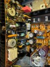
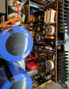
I only restore 2325s and have done this a dozen times. My workflow is based on AK members like LeeStereo, and I replace the recommended components for each receiver section(see attached pics).


Can you please pull off the 4-pin Molex connector and measure the voltages on the connector (red/blk/wht/yel or blu) for both sides?
LEFT
Red 63VDC
Black 0VDC
White -63VDC
Yellow 0VDC

RIGHT
Red 63VDC
Black 0VDC
White -63VDC
Blue 0VDC
Also, something doesn't make sense. On the R Channel, the white wire measures -52v at the connector, but +4.6v at R727?
I agree and double-checked voltage R R727 -51DCV.

I'm having contact issues on the right channel Molex; pin connectors were loose on the right side of the Molex and were not making good contact. I crimped them, and still, contact is intermittent unless u put pressure on the Molex, then the right amp stays on. I might have opened the contacts in the Molex too much when taking voltage readings.

The good news is I now hear a tone on the right side of the headphones and have signal output on the right speaker terminals. Using the signal tracer, I checked the signal at (L) J701 center RCA pin, and there is a tone.

Looks like voltage readings on the left channel are off at J710.


Where are you clipping the ground lead of the DMM when you measure, chassis?
Yes, I am clipping negative to the chassis.
 

Attachments

  • IMG_A7F36EF47DE7-1.jpeg
    IMG_A7F36EF47DE7-1.jpeg
    171.2 KB · Views: 10
  • IMG_F12718D37B20-1.jpeg
    IMG_F12718D37B20-1.jpeg
    181.1 KB · Views: 10
  • IMG_1AB01DBC7BE8-1.jpeg
    IMG_1AB01DBC7BE8-1.jpeg
    161.8 KB · Views: 10
Hi @dankik ,
I can't find the source of the voltage issues on the left amp P700. Referring back to your post #8 regarding the right and left amps, there is no output on the left channel and I'm getting voltage readings of 50VDC on the yellow wire comparing to 0VDC on the right amp blue wire. I have taken voltage readings on the left amp(see attached PDF) and am wondering if you think the cause of the voltage issues is the output transformers at H003 and H004. I am also reading 50VDC on the power supply pin J808 compared to pin J809 reading 0VDC. I appreciate your help:)

Richard
 

Attachments

You actually mean "...output transistors...", not transformers. ;)

Looks like almost all voltages are screwed-up. Try removing the 4 output transistors H001, H002, H003, H004 and re-measure some of the other voltages again and repost them. All 4 transistors may be shorted and sending the high voltage all over the board. When you have them out, put them on your transistor tester and let me know how they test.
1709448048035.png
Also, after removing the above transistors please measure the voltages for the L channel on J710 with the board plugged in. We know from before that unplugged they were OK at the connector.
 
You actually mean "...output transistors...", not transformers. ;)

Looks like almost all voltages are screwed-up. Try removing the 4 output transistors H001, H002, H003, H004 and re-measure some of the other voltages again and repost them. All 4 transistors may be shorted and sending the high voltage all over the board. When you have them out, put them on your transistor tester and let me know how they test.
View attachment 3136623
Also, after removing the above transistors please measure the voltages for the L channel on J710 with the board plugged in. We know from before that unplugged they were OK at the connector.
Transistors! I was cooked last night :oops:

I removed the output transistors, and they tested good using my Simpson 260.

Voltage readings are still messed up on the board.

By the way, I have replaced all transistors, caps, and diodes at H718, H729, H720, H721, and H717. Also, replaced resistors at R719, R720, R736, R743, R744, and film caps at C701, C708, and C709.

See the attached PDF of the voltage readings without output transistors installed.
 

Attachments

You have so many voltages wrong on the board, I'm not sure where you should begin.
What condition are the solder pads on the board... good or starting to lift. Do you have a solder removal gun or solder sucker?

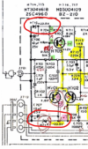
If we start at the beginning, H701(c) is at0 .7v.
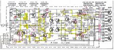
I don't know if Zener H717 (20.5v Zener) is pulling it down. It's -50v on the other side of R720, then gets pulled down to 0.7v on the other side.
Comparing it to the + side, you have the correct +20.5v (=21v).

1709489501642.png
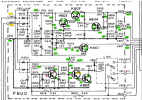
There are only 8 components connected to R720:
  1. R720 - Measure resistance and make sure it is not an open.
  2. C707 - First make sure of the cap polarity, + side goes to ground.
  3. H717 Zener - This is (I believe, a 20.5v Zener) remove and test for a short. Also, make sure it is installed in the correct direction: cathode (-) to ground.
  4. H705(e) - The last 5 are all connected so I'm not sure which could be the problem.
  5. R712
  6. C705
  7. R708
  8. H701(c)
1709488901833.png
Let me know what you find.
 
Last edited:
You have so many voltages wrong on the board, I'm not sure where you should begin.
What condition are the solder pads on the board... good or starting to lift. Do you have a solder removal gun or solder sucker?

If we start at the beginning, H701(c) is at0 .7v.
I don't know if Zener H717 (20.5v Zener) is pulling it down. It's -50v on the other side of R720, then gets pulled down to 0.7v on the other side.
Comparing it to the + side, you have the correct +20.5v (=21v).

View attachment 3136939
There are only 8 components connected to R720:
  1. R720 - Measure resistance and make sure it is not an open.
  2. C707 - First make sure of the cap polarity, + side goes to ground.
  3. H717 Zener - This is (I believe, a 20.5v Zener) remove and test for a short. Also, make sure it is installed in the correct direction: cathode (-) to ground.
  4. H705(e) - The last 5 are all connected so I'm not sure which could be the problem.
  5. R712
  6. C705
  7. R708
  8. H701(c)
View attachment 3136928
Let me know what you find.

You have so many voltages wrong on the board, I'm not sure where you should begin.
What condition are the solder pads on the board... good or starting to lift. Do you have a solder removal gun or solder sucker?
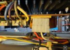
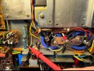
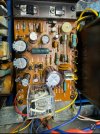
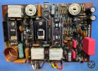
solder pads are in great condition, the amp has had little work done to it(see pic). I do have a solder removal gun HAKKO FR 301.
IMG_C16F544A7673-1.jpeg
IMG_B1E6EA27B46C-1.jpeg


If we start at the beginning, H701(c) is at0 .7v.
I don't know if Zener H717 (20.5v Zener) is pulling it down. It's -50v on the other side of R720, then gets pulled down to 0.7v on the other side.
Comparing it to the + side, you have the correct +20.5v (=21v).

  1. R720 - Measure resistance and make sure it is not an open.
    Voltage measurements 4.4VDC[expect -50] and 0.7VDC[0.7VDC]. I removed and resoldered. Found solder on one side was questionable. Resoldered and the voltages have changed a little on the output transistors and at J710. See attached PDF.

  2. C707 - First make sure of the cap polarity, + side goes to ground.
    Verified +cap is going to ground J701.

  3. H717 Zener - This is (I believe, a 20.5v Zener) remove and test for a short. Also, make sure it is installed in the correct direction: cathode (-) to ground.
    I replaced H717 before contacting you about the left amp. Continuity was not good, and I replaced it with 1N4747A.
    H717 anode reading 0VDC[expect 0VDC]. Cathode reading 0.7VDC[expect 20.5VDC].


    - The last 5 are all connected so I'm not sure which could be the problem.

  4. H705(e)
    Measured 0.7VDC [expect -20.5]

  5. R712
    Resistance Measured 10k Expect 10k. Measured 0.7VDC and 11VDC.

  6. C705
    Measured 1.3nf [expect 1000pf]. Measured 0.7VDC

  7. R708
    Measured 0.7VDC[expect -21.4VDC]

  8. H701(c)
    Measured 0.7VDC [expect -20.5]
 

Attachments

Last edited:
By the way, I have replaced all transistors, caps, and diodes at H718, H729, H720, H721, and H717. Also, replaced resistors at R719, R720, R736, R743, R744, and film caps at C701, C708, and C709.
solder pads are in great condition, the amp has had little work done to it(see pic).
Sorry, again I'm a little confused by the above statements. Just for clarification, all transistors were replaced, all caps replaced, 5 diodes, 5 resistors, and 3 more caps. Yet, you say little work done to it??
 
Back
Top Bottom