• The move to the new server is done. There are some software and database maintenance updates in process. This has us passing the hat around to help out. We appreciate any donations. Seriously, even a dollar helps. The payment page may be found here - https://www.audiokarma.org/support.html

Marantz 2325 P700 H706/707 Replacement

OFrank

Member
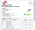
I have a Marantz 2325 for which I am replacing H706 and H707. I have read some posts and seen some pictures of the need to cross two legs of the replacement transistors. I have accomplished this with H707 (replacement KSC3503) but as I look at the data sheet for the original H706 (2SA818) and the new H706 (KSA1381), I noticed that I don’t need to cross the legs but simply flip the new transistor over.
My question is one of looking for confirmation from the group experts to ensure I am doing things correctly. The replacement transistors I got off a spreadsheet I found on this forum.
Thank you in Advance for the help.
O. Frank
 
Register to hide this ad
I was not comfortable crossing the legs/seemed like taking the easy way (or maybe not so easy) out.
I ordered Sanyo 2SA1209 (H706) and 2SC2911 (H707) taking some advice from some senior members.
Hope this helps.
 
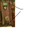
The layout of the OEM transistors H706/707 is EBC. Whereas the layout of the New /replacement transistors KSC3503/KSA1381 is ECB. So you have to swap the pins for both. Or buy a new board. Audio Karma member George has made a new board to fix the issue.
See Pictures.
 

Attachments

  • OldP700Board.jpg
    OldP700Board.jpg
    48.6 KB · Views: 37
  • NewP700Board.jpg
    NewP700Board.jpg
    112.1 KB · Views: 35
The layout of the OEM transistors H706/707 is EBC. Whereas the layout of the New /replacement transistors KSC3503/KSA1381 is ECB. So you have to swap the pins for both. Or buy a new board. Audio Karma member George has made a new board to fix the issue.
See Pictures.
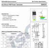
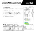
Here are the data sheets I have been using. The 2SA818 is pin1 - base, pin2 - collector, pin3 - emitter. The KSA1381 is pin1 - emitter, pin2 - collector, pin3 - base. Am I using wrong data sheet for the 2SA818 or is it incorrect?
 

Attachments

  • IMG_0117.jpeg
    IMG_0117.jpeg
    100.3 KB · Views: 16
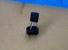
I use these stand offs sometimes.
They automatically do not let the legs touch.
I just put this one in as an example, finished and installed and straightened looks great.

IMG_2236.jpg
 
Take a look at my threadf on restoring the 2325. Post #30 takes you through completely updating the P700 Board. Crossing the leads on the transistors is not that bad, just use insulating tubing on one of the crossed leads to prevent them from touching.

 
Here are the data sheets I have been using. The 2SA818 is pin1 - base, pin2 - collector, pin3 - emitter. The KSA1381 is pin1 - emitter, pin2 - collector, pin3 - base. Am I using wrong data sheet for the 2SA818 or is it incorrect?
Just cross the pins as suggested by the members. I have done so in the past too. Looks like the confusion is from the datasheets.
 
Last edited:
Just investigating these substitutions here. So, here is what I found.
2SA818 vs KSA1381
1721439178684.png1721439253316.png

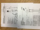
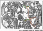
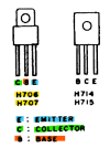
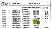
From the 2325 P700 schematic & PCB layout, it shows pads are CBE for H706/H707, and according to the leads diagram also on the schematic for H706/H707 it is CBE.
P700 transistors.jpg1721440609511.png
1721441104326.png

1721441433105.png

The datasheet (above) for the 2SA818 looks like it has the leads incorrect???
Can someone confirm this?
 
Just investigating these substitutions here. So, here is what I found.
2SA818 vs KSA1381
View attachment 3255249View attachment 3255250

From the 2325 P700 schematic & PCB layout, it shows pads are CBE for H706/H707, and according to the leads diagram also on the schematic for H706/H707 it is CBE.
View attachment 3255273View attachment 3255282
View attachment 3255291

View attachment 3255294

The datasheet (above) for the 2SA818 looks like it has the leads incorrect???
Can someone confirm this?
Interesting because on the original board (for the OEM Transistors) the pins are EBC for the old transistors and I assume that is right. As I have crossed the pins with the new 3503/1381 (ECB) by crossing B and C pins and it has worked fine. I may have to take a look inside the 2325 again. I also have both versions of the boards from George. I will need to dig them out. Its winter in Australia and so things are packed and stored away.
I believe the datasheet is wrong, Units I have repaired with those replacements with new boards and crossing pins with original board are working fine. Those transistors are definitely EBC, and the marking on the PCB is also correct, will need to look at the boards to reconfirm.
 
Last edited:
Back
Top Bottom