• The move to the new server is done. There are some software and database maintenance updates in process. This has us passing the hat around to help out. We appreciate any donations. Seriously, even a dollar helps. The payment page may be found here - https://www.audiokarma.org/support.html

Marantz 2325 project

sanjib

AK Subscriber
Subscriber
Register to hide this ad
The service manual states the original 15k filter caps were spec’d as +50%/-10%. So the top end acceptable capacitance with the original circuit design is 22.5k. And the good news is that modern +/-20% caps are usually on the low end of the scale. So your 22k caps will likely be 20-ish.
 
The service manual states the original 15k filter caps were spec’d as +50%/-10%. So the top end acceptable capacitance with the original circuit design is 22.5k. And the good news is that modern +/-20% caps are usually on the low end of the scale. So your 22k caps will likely be 20-ish.
Great to know! I will go-ahead with 22K.
Thank you
 
The date stamp on the front of the chassis rail is 1974 11 4. Is it a very early model? If yes, do I need to know anyhting in particular about the earlier models for restoration purposes?
Thanks
 
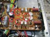
There may be some 2SC458 transistor and a 'gob' diodes on the phono board. KSC1845 are often used for the 2SC458s. The dual diode (the one between the two symetry 'pot') can be replaced with 21N4448's in series, the others with one 1N4448 each.
Search the Marantz forum for more info.
2325 Phono.jpg


These resistors run at blazing temperatures, be sure to get them up away from the board so the leads help act as a heat sink.
2325 PA Res.jpg

Good luck with your restoration, these are nice receivers!

Tom
 
There may be some 2SC458 transistor and a 'gob' diodes on the phono board. KSC1845 are often used for the 2SC458s. The dual diode (the one between the two symetry 'pot') can be replaced with 21N4448's in series, the others with one 1N4448 each.
Search the Marantz forum for more info.
View attachment 1826797


These resistors run at blazing temperatures, be sure to get them up away from the board so the leads help act as a heat sink.
View attachment 1826802

Good luck with your restoration, these are nice receivers!

Tom
Thanks a lot Tom! I first started the power supply board. I noticed the R804 in the manual says 10ohm 1/2W but on my board, it is 3.3ohm 5W ceramic installed (pic attached). I have some 10ohm 3W resistors (NTE brand) should I use it to replace R804? A couple of transistors are in bad shape I am planning to replace it. Is NTE brand okay for resistors?R804.jpg
 
Looking back at my pics, it looks like R804 is a 10 ohm, probably 1/2 watt (could be more). I didn't change it. Looks to me like yours is not original maybe?
IMG_1670_2.jpg
 
Steven, you are right it is not original. PCB is a little burnt under this resistor. I am thinking to replace it with the View attachment 1827436 original value 10ohm 1/2W.
I think that is what I would do. Then, when I fire it up I would keep a close eye for signs of overheating. If it does, something else around it is out of spec. Someone may have made it more robust to deal with overheating when something else is bad.
 
I usually replace the 2SD331 transistors on the heat sink with MJE15030, new mica and thermal compound.
The relay is probably suspect, too. Steven's board takes a (modern) LY type, yours may take an LY or an MY, check the hole size and spacing.

Tom
 
I usually replace the 2SD331 transistors on the heat sink with MJE15030, new mica and thermal compound.
The relay is probably suspect, too. Steven's board takes a (modern) LY type, yours may take an LY or an MY, check the hole size and spacing.

Tom
Tom
I have replaced 2SD331 with MJE15032G with mica and thermal paste. It has an LY type relay and I am going to replace it with a new one. I have also replaced all the diodes with
H808 DS-131B -MUR1620CTG
H809 DS-131B -MUR1620CTG
H810 WZ-140 -1N5244B
H811 WZ-071 -1N5236B
H812 1S2471 -1N4448

All the transistors H802-807 with matched KSC2383YTA and all the capacitors (except ceramic ones).

I am ordering the relay and the 10ohm 1W resistors and I have to wait until it arrives next week.
 
UPDATES and PROBLEM!!
The power supply is done and after installing it everything was running fine. Next, I did the PE01 board. I replaced all the electrolytic capacitors and all 250V rated film capacitors. After installing the board the left channel is working fine and the right channel volume is almost non-existent. When amp and preamp separated both channels in amp section working fine so I believe the problem is in preamp board. I decided to check the voltages at all pins of BA312 chip and compare it with the working channel. Below are the values (all values are measured on DBT with 150W bulb)

Pin bad channel good channel
1 2.475 V 2.07 V
2 0.2 mV 0.58 V
3 0.3 mV 62 mV
4 0.1 mV 0.1 mV
5 0. 95 V 0.6 V
6 3.16 V 17.7 V
7 33.85 V 33.85 V

I swap the BA312 but the problem did not swap channel (right channel still bad and left channel is good). So, I guess both BA312 chips are fine. I also checked the voltages at the emitter, base, and collector of H703-H706 and they are good as per the values in the schematic.
I need some help to move forward.
Thank you!
 
Last edited:
Little more update: the value of RE12 which is in the bad channel is 160ohm in the circuit but out of circuit it is 150K whereas, in the good channel the value of RE12 is 150K both in the circuit and out of the circuit. According to the schematic, the value of RE11 and RE12 is 150K. Any help will be great!
 
In the bad channel, the pin position 2 and 4 of BA312 is sorted on the board. I took out the BA312, RE112 and when checking the board it is showing sort between pin 2 and pin 4 position on PCB! In my naked eye with a magnifying glass, I did not see any connection between their traces! Is this the reason for the wrong voltages at pins??
 
Back
Top Bottom