• The move to the new server is done. There are some software and database maintenance updates in process. This has us passing the hat around to help out. We appreciate any donations. Seriously, even a dollar helps. The payment page may be found here - https://www.audiokarma.org/support.html

Marantz 2325 Protection relay HOT WIRED?

richardg0n

Active Member
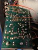
I bought a 2325 on eBay that has been serviced by a technician including a handful of times by my local repair guy who specializes in 70 stereos. Over the last year, the protection relay was replaced by my technician. The 2325 protection relay keeps clicking multiple times just after turning on the power. I now turn on the unit and wait 10 to 15 minutes before pushing the main speaker button and have no protection relay clicking issues once the unit warms up. Taking matters into my own hands because my technician couldn't replicate the problem I decided to recap the power supply and low and behold I find the power PCB damaged under the relay and what appears to be a hotwire job of the relay.

Should I replace the PCB before recapping? I don't think it's going to be easy to find a replacement PCB for the power supply. What would you do?

Thank you for your input,

Richard
 

Attachments
  • IMG_3136.jpg
    IMG_3136.jpg
    66.2 KB · Views: 82
  • IMG_3135.JPG
    IMG_3135.JPG
    75.1 KB · Views: 83
Last edited:
  • Like
Reactions: mbz
Register to hide this ad
What would you do?
Get the amp working normal.
Are the solder pads still ok? hard to see...
Remove jumpers/hacks, fit protection relay and the troubleshoot any issues in protect circuit and/or power amp stage

EDIT: welcome to AK
 
I dont know if this will help, but there are at least two different relays that were used in the 2325. Possibly a third, but I haven't seen it (If I remember). I would probably get the power board under good lighting and see if any traces are shorted/corrupted, and then make absolutely sure you did not accidentally short/open any of the caps you replaced. Also, check the foil under the cap, because sometimes you can screw it up when pulling an old cap and not realize it= and it ends up being an intermitant issue. In other words, loooooook verrrry carefully at what you did! Good luck!
 
The
Get the amp working normal.
Are the solder pads still ok? hard to see...
Remove jumpers/hacks, fit protection relay and the troubleshoot any issues in protect circuit and/or power amp stage

EDIT: welcome to AK


The PCB has huge holes where the relay soldering pads were located. Here is another closeup of the bottom.
 

Attachments

  • IMG_3137.JPG
    IMG_3137.JPG
    67.5 KB · Views: 67
somebody pulled it out incorrectly. You can mount the new one in there and manually wire it. Just make sure you get the right relay p/n.
 
Here is another closeup of the bottom.
Jumpers don't appear to bypass the relay, they simply provide a path due to damaged tracks.
Failing finding a replacement board (good luck) you might have to live with the jumpers. Next step is
to work out why the relay is cycling, could be excessive dc voltage or fault in protection circuit.
Measure/monitor dc voltage after power on at J808 on protect board, black probe connected to chassis, repeat for J809.
Expect some immediate transients, only interested after the mute period, typically after 4-8 seconds
 
Jumpers don't appear to bypass the relay, they simply provide a path due to damaged tracks.
Failing finding a replacement board (good luck) you might have to live with the jumpers. Next step is
to work out why the relay is cycling, could be excessive dc voltage or fault in protection circuit.
Measure/monitor dc voltage after power on at J808 on protect board, black probe connected to chassis, repeat for J809.
Expect some immediate transients, only interested after the mute period, typically after 4-8 seconds

mbz,
I have the unit plugged into a Dim Bulb Tester.
J808 Shot up to 3.5v before the protection relay clicked and backed down to 0v.
J809 Shot up to 4.0v before the protection relay clicked and backed down to 0v.
 
You probably need to switch to the mV scale. 3.5-4V during the mute period is no concern.
Ideally both should be less than 10mV after mute though less than 50mV is still ok. Fact that relay clicked means there was
no excessive dc voltage. Are you able to replicate the cyclic switching of the relay, need dc voltages at this time
to confirm it's a power amp problem
 
You probably need to switch to the mV scale. 3.5-4V during the mute period is no concern.
Ideally both should be less than 10mV after mute though less than 50mV is still ok. Fact that relay clicked means there was
no excessive dc voltage. Are you able to replicate the cyclic switching of the relay, need dc voltages at this time
to confirm it's a power amp problem

Got it.
J808 holding under 10mV after mute. The DMM reading increases slightly when I turn up the volume but stays under 10mV. Dim bulb tester gets brighter after four to five minutes.

J809 holding under 10mV after mute and the volume turned down. The DMM reading increases as I turn up the volume. I increased volume to 10 o'clock position and DMM read 480mV. Dim bulb tester gets brighter after four to five minutes and DMM measurement fluctuates +/- 400mV(480mV to 800mV).

I am able to replicate cycle switching roughly five minutes after initial power, with or without speakers engaged, the speakers must be connected to the unit. I can tell the relay is cycling when the unit makes a loud pop/sizzle sound through the speakers(when I have the speaker buttons engaged) and the sound drops out but the unit remains powered on. Five minutes later the relay cycles on.
 
  • Like
Reactions: mbz
Good news, often such intermittent problems are difficult to reproduce
making troubleshooting a PITA. 480-800mV is enough to trip protection.
Problem is with power amp, left channel.

I'm not real familiar with marantz receivers, best to wait for one of the
marantz guys. My next step would be to monitor voltages on the P700 board.
Maybe play through headphones or some junk speakers.

Suggest get a baseline before the problem occurs. Measure dc voltages at
- H708base (R754, R730) +0.6V
- H709b (R731 or R740, VR wiper) -0.6V
- H001c (J708) +15mV
- H003c (J702) -15mV

Then recheck voltages once the amp goes in protection.

Don't probe transistor legs, one slip... Probe a part connected to the same
node, shown in () above.

As a punt, issue might be temperature related so heatsink items come into play.
Would expect some thermal compensation of bias, possibly H715 heat sink mounted???
 
Good news, often such intermittent problems are difficult to reproduce
making troubleshooting a PITA. 480-800mV is enough to trip protection.
Problem is with power amp, left channel.

I'm not real familiar with marantz receivers, best to wait for one of the
marantz guys. My next step would be to monitor voltages on the P700 board.
Maybe play through headphones or some junk speakers.

Suggest get a baseline before the problem occurs. Measure dc voltages at
- H708base (R754, R730) +0.6V
- H709b (R731 or R740, VR wiper) -0.6V
- H001c (J708) +15mV
- H003c (J702) -15mV

Then recheck voltages once the amp goes in protection.

Don't probe transistor legs, one slip... Probe a part connected to the same
node, shown in () above.

As a punt, issue might be temperature related so heatsink items come into play.
Would expect some thermal compensation of bias, possibly H715 heat sink mounted???


I plugged in headphones, volume at 10 o'clock, and the main speaker button engaged.

R754 - Baseline 5mV (before relay engages) - After relay engages 5mV
R730 - Baseline 88mV - after relay engages fluctuates 1.9V-5V

R731 - Baseline 70mV - after relay engages fluctuates 2.5V-4.2V

J702 - 1.7V baseline - after relay engages a series of events occurred. After five minutes headphone sound faded out, dim bulb brightness increased to very bright, DMM 125mv-1.7V, DIm bulb brightness dropped to low and DMM stayed under 50mV before returning to very bright and DMM 125mV-1.7v. relay did not cycle during this test.

J708 - Baseline 73mV then dropped to 0mV. Relay never cycled during this test

Other observations - The left side is running much warmer. The right side is running cool. Relay cycled after 10 minutes and sound from headphones stopped after five seconds.
 
Do you have a can of freeze spray?
EDIT: Suggest when the amp goes into protect, give a transistor a short
spray and wait for upto 30 seconds and note effect. Candidates are
H706, H707, H714, H715, H708, H709
 
With the 2325 powered down, connect the pre-amp out and power amp in RCA connectors at the back using good interconnects and move the RCA connectors in and out multiple times. Turn the receiver on to see the popping sound still persists. It happened to my 2325 couple times in the last 15 years. I found that the silver plated RCA connectors were covered with black silver oxide which needed cleaning to kill the popping sound.
 
  • Like
Reactions: mbz
See edit, post 13.
Seems like something is failing under load, remove the load (by relay open) and the offending part cools down
and behaves as it should. Try some direct cooling...

I finally found a fix. I replaced the two small transistors H706 and H707 on the left channel amp. I had to use newer transistors and crossed two of the pins. I also recapped and replace several other components after fixing the problem.
 

Attachments

  • IMG_0546.JPG
    IMG_0546.JPG
    143.8 KB · Views: 33
Back
Top Bottom