• The move to the new server is done. There are some software and database maintenance updates in process. This has us passing the hat around to help out. We appreciate any donations. Seriously, even a dollar helps. The payment page may be found here - https://www.audiokarma.org/support.html

Marantz 250 bias (V1,V2,...,250m)

elgrillo

El Grillo
Hello I have a doubt about biasing different versions of Marantz 250 power amp.

1) I note that there is a version 1 (mk1) that the manual specify to bias the amp with a wattmeter and a voltmeter.

2) As seen on bulletin m-250-3 the specify to adjust bias using a multimeter reading Mv (between 24-30mv) across R531 & R532.
In service bulletin m-250-4 they also specify adjusting bias with a multimeter in the same resistors but between 12-15 mv.

Im trying to bias my Marantz 250 (mk1) using the method of the bulletins because I don't have a wattmeter. but the bias drifts. Normally it stays around 13 mv, sometimes it can go up up to 17mv or down till 10 mv.

My question is , as the mk1 was the first version of all , is this one is prone to drift bias a little more , and that is why they made the revisions?

I saw a video in youtube of a guy restoring a Marantz 250m and when he biased the amp, the amp stabilized really nice in 12Mv and didn't drift more than a few decimals.

My Marantz have been recapped , new transistors replacements, and a few new resistors on the amp boards . I changed some resistors on the power supply, al caps and changed the relay and diodes. I just left the original transistors transistors.

Maybe somebody that worked on all versions can tell about the difference on bias stability between the different versions of the Marantz 250.

Thanks in advanced.

Gonzalo.
 
Register to hide this ad
My thoughts on 'bias'.
You need enough 'bias current' to keep the output section(s) of the amplifier in class AB operation at idle and when in operation.
Most times, as the output section heats up (in use), the forward current transfer ratio (current gain) of the semiconductor devices increases, eventually leading to thermal runaway and destruction.
In a perfect circuit, temperature compensation would correct the 'bias' current to maintain it exactly where it was set at all temperature ranges experienced by the amplifier.
Since nothing is perfect, perhaps a good goal would be to insure there is enough bias current to maintain class AB operation when the amp is at any expected temperature.

I don't think a small variation in bias current is going to cause your amp to fail. I would be more concerned about other factors such as hypersonic oscillations and poor heat management issues.
Remember, speakers are a reactive load while a dummy load should be pure resistance.

Tom
 
My thoughts on 'bias'.
You need enough 'bias current' to keep the output section(s) of the amplifier in class AB operation at idle and when in operation.
Most times, as the output section heats up (in use), the forward current transfer ratio (current gain) of the semiconductor devices increases, eventually leading to thermal runaway and destruction.
In a perfect circuit, temperature compensation would correct the 'bias' current to maintain it exactly where it was set at all temperature ranges experienced by the amplifier.
Since nothing is perfect, perhaps a good goal would be to insure there is enough bias current to maintain class AB operation when the amp is at any expected temperature.

I don't think a small variation in bias current is going to cause your amp to fail. I would be more concerned about other factors such as hypersonic oscillations and poor heat management issues.
Remember, speakers are a reactive load while a dummy load should be pure resistance.

Tom
Thanks Tom, now I understand more about biasing, my only doubt is if the mk1 board like mine its less stable than the other revisions and if there is something to tame it down on the bias .

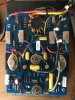
This is my amp board. There is no CR503 on my circuit (germanium diode across the bias pot)

IMG_2081.JPG
 
Thanks Tom, now I understand more about biasing, my only doubt is if the mk1 board like mine its less stable than the other revisions and if there is something to tame it down on the bias .

This is my amp board. There is no CR503 on my circuit (germanium diode across the bias pot)

View attachment 1729437
I know this is an old thread but the germanium diode is right there on top of the right predriver involved in shrink tubing.
 
New to audio repair. I have a Marantz 250 with SN 10228. Which version is that? I have adjusted the bias to 13 mV, the amp plays OK at beginning, the audio in Rt channel will in and out after 30-40 min. The heat sink remains cold to touch in both channel. Preamp is Marantz 3300. and volume is about 10 o'clock. I found the Service Manual on HiFiengine, it mentioned to adjust the bias with Wattmeter. Any suggestions? Thanks.
 
Does it have the 4 rectifying diodes on top of the filter caps? How old/new is the relay?
 
New to audio repair. I have a Marantz 250

i'm impressed you are new and working on this amp. i found it one of the more difficult amps to repair and maintain.

I found the Service Manual on HiFiengine, it mentioned to adjust the bias with Wattmeter. Any suggestions?

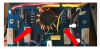
I'd suggest either adjusting the bias per @elgrillo or here. here is a pic of where I measured the bias. I'd dial it to 15mV - 20mV. And check on a scope for any cross over distortion.

I've only done 4 or 5 so by no means an expert.

Good luck!

upload_2022-3-28_9-31-57.png
 
Back
Top Bottom