R&B Stereo
New Member
Greetings AK friends,
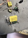
First time posting here, but longtime admirer of this site. I do have a side biz in vintage stereo repairs, and many years under my belt. And while constant learning is part of the process, sometimes one comes across a real head scratcher. I am restoring a Marantz model 250 (not the M) for a client and I came across a busted “what appears to be” a BWH resistor on the board. It’s not just a resistor but I would call it a “contraption” (has another resistor and capacitor in series and another capacitor in parallel attached to it). I say “appears to be” as the schematic only seems to refer to a 1ohm 2W BWH resistor. The “contraption”, which by the way appears from factory, from the good power board, has a ‘carbon’ resistor reading 100ohms, another 10ohms in series along with a 0.1uF capacitor, and a 6800pf capacitor in parallel. If you’re my age, it takes you right back to “the thing” horror movie. I have done some research and watched some YouTube on this model but I don’t recall coming across a suitable replacement for such. Would a 1ohm / 2W BWH resistor replacement be good enough, per the service manual? Many thanks in advance.
First time posting here, but longtime admirer of this site. I do have a side biz in vintage stereo repairs, and many years under my belt. And while constant learning is part of the process, sometimes one comes across a real head scratcher. I am restoring a Marantz model 250 (not the M) for a client and I came across a busted “what appears to be” a BWH resistor on the board. It’s not just a resistor but I would call it a “contraption” (has another resistor and capacitor in series and another capacitor in parallel attached to it). I say “appears to be” as the schematic only seems to refer to a 1ohm 2W BWH resistor. The “contraption”, which by the way appears from factory, from the good power board, has a ‘carbon’ resistor reading 100ohms, another 10ohms in series along with a 0.1uF capacitor, and a 6800pf capacitor in parallel. If you’re my age, it takes you right back to “the thing” horror movie. I have done some research and watched some YouTube on this model but I don’t recall coming across a suitable replacement for such. Would a 1ohm / 2W BWH resistor replacement be good enough, per the service manual? Many thanks in advance.