• The move to the new server is done. There are some software and database maintenance updates in process. This has us passing the hat around to help out. We appreciate any donations. Seriously, even a dollar helps. The payment page may be found here - https://www.audiokarma.org/support.html

Marantz 250 rebuild

rickl

I'm just a bass player
Subscriber
My uncle gave me his old Marantz 250, serial number 1105. He included a bunch of documentation including service manual, service bulletins, and the original receipt ($420 in 1971). I'd really like to get it working for him.

I've read up on these on this site and it looks like a tough one to fix. Hopefully I can get it working with the help from this site.

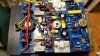
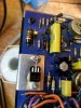
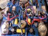
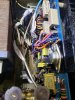
One channel of the speaker relay is burned up and fused together. I measured the resistance of the outputs on the burned side and they appear shorted (C-> B 0, E->B 0, B->E 0, C->E 0 for the SJ2519 and C->B , E-B open, B->E open, C-E open on the SJ2502). Also attached are a few pics of various voltages.

The plan is to get new outputs (OnSemi MJ21193/21194) and electrolytic caps from Mouser or DigiKey. And a new OMRON MY2IN relay with updates from ChrisMarantz.

Should I replace the drivers too (SJ2515/16)? Do I just measure the resistance between the EBC?

I only have a variac, scope, DVM, and function generator so my troubleshooting might be limited.

I fix a lot of tube guitar amps so this is my first SS amp (unless you count all the Hafler gear I've worked on).
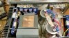
20161005_204532.jpg 20161008_142607.jpg 20161005_204519.jpg 20161005_204512.jpg

Another 250 restore using modern (2021) transistors can be found here.
 
Last edited:
Register to hide this ad
Silly question but does the other channel work?

you're going to have to start with at the least testing every transistor on that board. Obviously start with the ones nearest the output. The 250 has a funny way of eating itself just when you think you have it all figured out. And don't forget the PS board caps.
 
It might be better to use the "diode" function to check the transistors and Airtime's advice is spot on to check everything before a repower. There's a sticky thread over in the DIY subforum on how to do that.

Also, even with a variac, I recommend using a "Dim Bulb Tester" (DBT) when you do attempt a power on. Good on you for doing research already!
 
Thanks Charles, Tom, and Mr. Buckner. I haven't tried powering up the amp to see if the other channel works. I'll test the other transistors and update the caps.

I'll post my findings.
 
Sure thing Rick and call me Randy (just not Shirley!)
images
 
Not sure if this is a necro post since I'm the OP but I've set this on the shelf until I had a bunch more SS restores completed, DBT built, transistor tester, and a bit more courage.

nothing like being a tech for a local shop to get your feet wet and fix all kinds of stuff.

I'm currently focused on getting one amp board working.

I did recap the relay board and installed a new relay per ChrisMarantz.

I've replaced the outputs (MJ21193G/MJ21194G)
Q505 with a MPSA65
Q503, PNP SPS1952 with a BC560C
Q507 and Q508 with 2N5415/2N3440 pair. For some reason both Q507 and Q508 where SS9305 (NPN)
All new electrolytic caps per other 250 threads found on AK.

Since I don't know the history of this amp, I just replaced both Q507/Q508 with correct NPN/PNP pair.

I fired it up with a DBT, relay clicked, and got big signal out with little signal in. Pretty excited. It has been since late 90s or early 2000 since this has been working. Still need to check bias and DC offset.

I looked at the other channel and found the missing PNP. Both Q507 and Q508 are PNP. Not sure if this was a prior repair but it did fry Q508 emitter resistor. I'll replace both with the 2N5415/2N3440 pair.

I hope to get the other channel working.

250-A-scope.jpg
 
Last edited:
The 'B' channel isn't being easy. none of the outputs were blown but one PNP only have a hFE 10. All will be replaced with MJ21193G/MJ21194G.

As stated above Q507/508 where swapped to the other channel so both PNPs where on this channel. these where swapped out for 2n5415/2N3440 like channel A.

Q506 is bad. 2N4123. Looks like a MPSA20 is a modern sub. Mouser has a few. If the link is true, the complement to a MPSA20 is a MPSA70. footfungus says 2N5078 is the same thing. Is this true? Looking at the specs they don't look close.

I'll get a few of each for each channel and match them up.

driver Q511 is bad. SJ2516. Plus in a TO-66 case :eek:. I've read to use MJE15030/31 for Q510/Q511. Anyone know?

My plan is to order
MJE15030/31 drivers
Q505 (2N4125) - 2N5078. Or a 2N3906. See this. Will 2N5078 work?
Q506 MPSA20 pre-drivers but don't know the complement that is avaliable.

Thanks for any help.

a pic is always nice. here is a burned up 47R resistor :)
250-47R.jpg
 
Last edited:
Order came in.

I replaced the Q511 with a MJE15031, Q506 with a MPSA20, and outputs with with MJ21193G/MJ21194G, added the diodes per service bulletin. and the channel is working.

Still need to set bias but this is great. I'll hook up both channels and meters and let it soak.
 
Last edited:
here is a pic for Q511 replacement. the original is a to-66 but now obsolete.

i used a solder lug on an insulated bolt. i also used some t03 bolt shoulder washers for the base and emitter pins to isolate them from the heat sink.

q15-to220.jpg
 
Last edited:
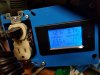
I think I got the bias set. The service manual says to bias each channel separately using a watt meter. I built one from an amazon board and plugged it between my variac and amp. Inputs shorted, 8R load.

Reading thread on AK I found Chrismarantz's post.
Usually the cases will measure between 19mV and 24 mV. I have settled on 22 mV for the bias on models 250​

I added a volt meter between collector side of R537/R538 (330R) and dialed up the variac to house voltage (121vac). Dialed bias pot (R526) to 20mV. Watt meter is nice to monitor variac voltage, current, and watts.

I let it soak for over an hour with out any runaway or magic smoke.

here is a pic of the watt meter with each channel bias set to 20mV.

250 watt meter.jpg

Kind of hard to see but here are the bias points I used for each channel. Please use mini grabbers with power off.

250-bias-points.jpg
 
Last edited:
I finally adjusted the dc balance per assembly manual and rechecked the bias. connected speakers and a preamp and was playing music. Still need to let it play for a while but kind of nice to get it working. one of the meter bulbs flickers but seems like a common problem.
 
i'm helping @elgrillo on his Marantz 250 and noticed I didn't include a few things on this thread.

I replaced the large PS caps to remove a hum from both channels. I used E32D800HPC223MD79M from digikey. they are shorter but have the same diameter. They seem to work fine.

I also used #47 bulbs for the meters. I figured the 200mA savings couldn't hurt.

 
Hey Rickl, thanks for the help by the way. I see the photo you post showing the resistors points for biasing. I think you are checking on the wrong resistors. The good ones are the big ones that look like metal springs just a side of the resistors you are using . Im pretty sure you are mistaken. Im still working on my 250 to get still biasing readings. I already change some resistors but the problem continues. My next step is to change Q510 & Q511 with MJE15030G &MJE15031G
 
Hey Rickl , if you have some time could you be kind to mail me the 250 schematics? I have one that I downloaded from the web and are very very blurry and very difficult to read.

Thanks in advanced.

Gonzalo.
 
Hey Rickl, thanks for the help by the way. I see the photo you post showing the resistors points for biasing. I think you are checking on the wrong resistors. The good ones are the big ones that look like metal springs just a side of the resistors you are using . Im pretty sure you are mistaken. Im still working on my 250 to get still biasing readings. I already change some resistors but the problem continues. My next step is to change Q510 & Q511 with MJE15030G &MJE15031G

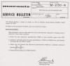
To backup what I said about biasing , here in the attach some info from the service bulletin M-250-4, It also says that bias should be between 12 and 15 mv. Hope this help.
 

Attachments

  • Screen Shot 2020-01-09 at 7.06.17 PM.png
    Screen Shot 2020-01-09 at 7.06.17 PM.png
    479.1 KB · Views: 96
I've got three 250's sitting on the shelf waiting on me to start. Serial # 3473, 3503 and 3977. None have been tested and one has wires to the amps cut. I'm an older NOOB who collected and researched until my recent retirement. Just got my Pace solder sucker rebuild and it works great for a 40 year old station. Have started rebuilding on 2- 2215B's, 2230, 2270-4220-4240, 4070 and 4300. I'm working my way up from easy to hard. Finally understanding Marantz better, Boards and Manuals. PEO1 is usually preamp, 400 phono, 700 amp and 800 power supply. Can look now and determine board functions. Read all the cap posts too. Got a big Mouser order started. Want to finish the Marantz stuff before I get into the Sansui's.

I made a BOM in 2018 and put the work on hold until I get more experience. I had no replacement for Q504 and no Mouser parts #'s for Q505 and Q 506. The 250 manual uses a lot of Marantz part numbers so you have to get part numbers off the parts on the boards. I just updated my BOM and have one more question. My old part number for Q507 was 2N5416 and 2N5415 was used above. Looked up the specks and 2N5416 is a higher rated version of 2N5415. I just looked up the part number for Q507/ 2N5416. Back ordered and $8.75 each. Checked on the 2N5415 and it was $23 each on Mouser. I'll go cheap here. Sorry, looked again and found them for $2.42 way down the list. Still learning.

Here is my BOM. I'd like to keep this discussion open until I can get these fixed. Opened all three up and one set of boards has burnt resistors and the other two don't have visual damage. All the Q802 to Q805 transistors failed, Q510 and Q511 failed and Q507 and Q508. Resistors R543 and R529 are burnt. I'll get new parts ordered and look up the fix for Q510 and Q511 conversion from TO66 fix. I can use the picture above but need to figure out how its connected with the middle leg. I looked at the data sheet and pin 2 and the back are tied together. You can cut the center pin and use the back plate as the connection to the board with screws. I've got this on a 4070 Marantz. See the photo. I'll update once I get the parts in.
 

Attachments

  • 20210203_163803.jpg
    20210203_163803.jpg
    148.3 KB · Views: 137
  • 20210203_163627.jpg
    20210203_163627.jpg
    167.7 KB · Views: 139
  • 20210203_163803.jpg
    20210203_163803.jpg
    148.3 KB · Views: 136
  • 20210203_155543.jpg
    20210203_155543.jpg
    129.4 KB · Views: 136
  • 20210203_210354.jpg
    20210203_210354.jpg
    79.6 KB · Views: 136
Back
Top Bottom