• The move to the new server is done. There are some software and database maintenance updates in process. This has us passing the hat around to help out. We appreciate any donations. Seriously, even a dollar helps. The payment page may be found here - https://www.audiokarma.org/support.html

Marantz 250 restoration query

quadmatrix82

AK Subscriber
Subscriber
Hi Marantz gurus, I’ve started restoring my Marantz 250 - have been reading up on the numerous threads here how people go about it and wondering is the fly back diode mod detailed in the service bulletin mandatory for any Marantz 250? or is it for certain ones pending their serial number? My serial number is 4004 , thanks in advance for your help!
 
Register to hide this ad
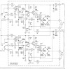
Thanks! Looks like I have a later board than the one mentioned in the service bulletin 3 - I found another post how this was done by another member instead is this correct if I replicate for my board with U4007?
If they are not present, install some.
YMMV

Tom
 

Attachments

  • BF2D3164-CA82-4B91-A3EA-662F71E3ECDB.jpeg
    BF2D3164-CA82-4B91-A3EA-662F71E3ECDB.jpeg
    167.7 KB · Views: 131
  • 8177448A-59D6-4F51-BDCB-71D2B06DF82B.jpeg
    8177448A-59D6-4F51-BDCB-71D2B06DF82B.jpeg
    84.2 KB · Views: 128
  • 241AD3E4-B777-469E-AF03-A8F6E3700B12.jpeg
    241AD3E4-B777-469E-AF03-A8F6E3700B12.jpeg
    123.1 KB · Views: 125
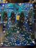
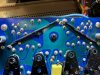
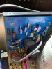
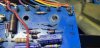
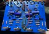
so I put the diodes on today - did I connect them to the right spots? diode on LHS connects to the 39ohm resistor
 

Attachments

  • flyback diode marantz 250.jpg
    flyback diode marantz 250.jpg
    122.4 KB · Views: 100
  • 39ohm resistor.jpg
    39ohm resistor.jpg
    81.8 KB · Views: 90
Starting to go through the rest of the amp and I have a few other queries -

Main amp board - Version A/W 115 1022 Rev F

Q520 - MPSA20 I noticed the new replacement has much lower gain than the original - is this OK?

Q501/502 - should these be shrink wrapped with thermal paste? on both channels they don't seem to be wrapped together - maybe someone removed it previously? again i noticed the gain on the old transistors is higher than the new ones - is this a concern or is the primary aim to match them only?

Flyback diodes - what are the correct connections to attach the diodes to? The service bulletin procedure references a different board so want to make sure i connected to the correct points on both diodes.

Output transistors - one side has the original outputs still in place, is it recommended to keep these here or match both channels with MJ21193/94g? both channels have original drivers still.

Meter board - Version A/W 115-1030 Rev A
MPSA20 are coded orange - what does the orange colour denote? Do these transistors need to be gain matched with the other transistors on the board? I have new MPSA20 available to refit

Thanks!
 
Last edited:
Starting to go through the rest of the amp and I have a few other queries -

Main amp board - Version A/W 115 1022 Rev F

Q520 - MPSA20 I noticed the new replacement has much lower gain than the original - is this OK?

Q501/502 - should these be shrink wrapped with thermal paste? on both channels they don't seem to be wrapped together - maybe someone removed it previously? again i noticed the gain on the old transistors is higher than the new ones - is this a concern or is the primary aim to match them only?

Flyback diodes - what are the correct connections to attach the diodes to? The service bulletin procedure references a different board so want to make sure i connected to the correct points on both diodes.

Output transistors - one side has the original outputs still in place, is it recommended to keep these here or match both channels with MJ21193/94g? both channels have original drivers still.

Meter board - Version A/W 115-1030 Rev A
MPSA20 are coded orange - what does the orange colour denote? Do these transistors need to be gain matched with the other transistors on the board? I have new MPSA20 available to refit

Thanks!

Your board looks to be an early revision, the gain of Q501/502 is critical for determining DC offset and then due to a design quirk, the bias. If the gain is too low you'll get no bias, I had to go with extremely high gain parts in my unit to get it working.

Modern MPSA20s work fine to replace the original one.

It is highly recommend (honestly required if you plan to use the 250) that you pull the driver, predriver and output Transistors and test each for gain, if they are not within the proper gain range as defined by the Marantz service bulliten both the bad Transistor and it's complement needs to be swapped and matched. I have seen units where they "worked" but several of those higher power Transistors were nowhere near spec and it was only a matter of time until the 250 nuked itself.

 
Your board looks to be an early revision, the gain of Q501/502 is critical for determining DC offset and then due to a design quirk, the bias. If the gain is too low you'll get no bias, I had to go with extremely high gain parts in my unit to get it working.

Modern MPSA20s work fine to replace the original one.

It is highly recommend (honestly required if you plan to use the 250) that you pull the driver, predriver and output Transistors and test each for gain, if they are not within the proper gain range as defined by the Marantz service bulliten both the bad Transistor and it's complement needs to be swapped and matched. I have seen units where they "worked" but several of those higher power Transistors were nowhere near spec and it was only a matter of time until the 250 nuked itself.

Thanks for your help and good advice there - I checked q516/7 and the hfe was way off on each of them 60 and 103...i'll start to check the others i suspect could be similar with all of them given their age...

will report back with an update shortly
 
Started to change the film caps on the power amp board, awaiting on the additional transistors and caps before I proceed further.

Plan is to finish one channel first, test and then repeat on the second - someone had been through this board before and unfortunately singed a few bits - cleaned it up best I could at least the rear traces are very clean with no broken tracks.

I marked in this photo the spots the flyback diodes are positioned on the rear - are these the correct points?
 

Attachments

  • IMG_4851.jpg
    IMG_4851.jpg
    177.4 KB · Views: 98
Last edited:
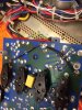
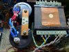
Rectifier diodes and capacitors replaced on the protection board - rectifier diodes are 6amp HER605G as recommended from another restoration thread.

The relay looks like its been replaced before, it was working OK so I'll leave it for now
 

Attachments

  • IMG_4847.jpg
    IMG_4847.jpg
    69.8 KB · Views: 85
always a great day when you get a mouser delivery! most of my parts for the restoration have now arrived, how important is it to gain match Q505 and Q506?

I ordered 2n3904 and 2n3906 and the closest i got for one pair is 5 hfe difference and the others ~25 hfe difference - the service manual doesn't list that these need to be gain matched but i note the originals were colour coded red so assume they were initially matched at factory? Thanks in advance for your help
 
Filter caps installed - making slow progress doing what I can whilst waiting for parts. I used EPCOS 22,000uf which are the same diameter as the original 20,000uf caps making for a fresh OEM look.
 

Attachments

  • filter caps marantz 250.jpg
    filter caps marantz 250.jpg
    137.3 KB · Views: 59
Does anyone have a recommendation for a replacement diode that is on the meter board labelled as MM-8005 (marantz part 460-1009) - one looks damaged on the board but still test OK.
 
460-1009 crosses to an NTE177, a common rectifier, 1N4009 might work
A photo or schematic might help.

Tom
 
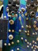
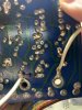
Thanks Tom here’s a photo, someone tried to repair this board previously there’s a diode on the trace side that looks like a replacement but I can’t identify it. I’ve replaced all the zener diodes and capacitors on this board already and also one of the 2.2k resistors as someone had previously incorrectly fitted a 2k resistor.
 

Attachments

  • 514B7048-5968-469B-B449-38E715D7A5D9.jpeg
    514B7048-5968-469B-B449-38E715D7A5D9.jpeg
    79.6 KB · Views: 86
460-1009 crosses to an NTE177, a common rectifier, 1N4009 might work
A photo or schematic might help.

Tom
Additional photo of the board and trace side
 

Attachments

  • 12171CD9-BF06-4736-B318-22EDFAD7527D.jpeg
    12171CD9-BF06-4736-B318-22EDFAD7527D.jpeg
    102.7 KB · Views: 72
  • DA175E40-A18A-4373-BFBA-918F54FBF430.jpeg
    DA175E40-A18A-4373-BFBA-918F54FBF430.jpeg
    129.5 KB · Views: 76
The black ones look like regular rectifier diodes, 1N4007 should be OK.
The two next to the big resistors are Zener diodes, 13V 1W (1N9648) IIRC.
The others? You will probably have to find someone who knows more about it than I.

Tom
 
The black ones look like regular rectifier diodes, 1N4007 should be OK.
The two next to the big resistors are Zener diodes, 13V 1W (1N9648) IIRC.
The others? You will probably have to find someone who knows more about it than I.

Tom

Thanks Tom - i've replaced the zener diodes already they were 1N964B and 1N753A and replaced the capacitors on the board.

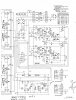
I'll get the 1n4007 as you suggest for MM8005 and install once I get the rest of the amp running. Here's a snip of the diagram of the meter board
 

Attachments

  • Screenshot 2021-06-18 191751.png
    Screenshot 2021-06-18 191751.png
    174.8 KB · Views: 16
If the MM8005 are in the bases of the meter drivers and the bridge rectifier for the meters, I doubt IN4007 will work.

M250 meterbw06182021_0001.jpg
 
Perhaps 1N270 would work, you may have to replace all four in that bridge, CR404, CR405, CR407 and CR408

Tom
 
Back
Top Bottom