sstudley
Member
Posting for my friend, and for general edification:
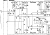
“The Marantz 250(M) amplifier inputs have a voltage, appearing on post #2, whose purpose is not entirely clear to me, as an amateur electronics enthusiast of modest technical knowledge. I’m hoping someone with real EE chops can clarify the function of this circuit node.
Basically, the aforementioned post #2 voltage is ultra close to ground, and appears to be slightly higher impedance, heavily bypassed to ground, and otherwise no different from ground. Its sole purpose appears to be to bias various transistors. My expectation is that many would look at this and think “Hmm, this looks like a less noisy, ‘filtered’ ground.”
On closer examination, I doubt this intuition, though as mentioned, I am no EE. Again, this semi-ground has higher impedance than actual ground (though it is still quite low), and any noise that might be present on ground should be coupled fairly directly via the tantalum capacitor (albeit subject to the tantalum’s nonzero ESR). Furthermore, it seems possible that any differences between this point and ground would show up as ground noise injected into the power stage, as a difference between the output transistor’s “noise free” version of the input signal, and later stage ground (but a complete analysis would also consider the supply rails, and seems rather involved).
It is certainly possibly, and maybe likely, that I’m misunderstanding the purpose of this circuit node. I would appreciate any insights that those who fully understand the circuit can impart, in terms accessible to the amateur electronics dabbler.”
(End of friend’s question.)
As a side note, I have repaired numerous such amps, and have noted the general tendency of these amps toward some level of instability. Although much of that instability appears to be related to bias and DC offset, and presumably is a byproduct of somewhat less sophisticated biasing and temperature compensation, my loose hunch is that the front end seems somehow to be the source of some of the instability. Adding to my friend’s question, I speculate that this pseudo-ground could have something to do with the problem.
Definitive insights into the purpose of this pseudo-ground will be gratefully received. Thanks in advance!
“The Marantz 250(M) amplifier inputs have a voltage, appearing on post #2, whose purpose is not entirely clear to me, as an amateur electronics enthusiast of modest technical knowledge. I’m hoping someone with real EE chops can clarify the function of this circuit node.
Basically, the aforementioned post #2 voltage is ultra close to ground, and appears to be slightly higher impedance, heavily bypassed to ground, and otherwise no different from ground. Its sole purpose appears to be to bias various transistors. My expectation is that many would look at this and think “Hmm, this looks like a less noisy, ‘filtered’ ground.”
On closer examination, I doubt this intuition, though as mentioned, I am no EE. Again, this semi-ground has higher impedance than actual ground (though it is still quite low), and any noise that might be present on ground should be coupled fairly directly via the tantalum capacitor (albeit subject to the tantalum’s nonzero ESR). Furthermore, it seems possible that any differences between this point and ground would show up as ground noise injected into the power stage, as a difference between the output transistor’s “noise free” version of the input signal, and later stage ground (but a complete analysis would also consider the supply rails, and seems rather involved).
It is certainly possibly, and maybe likely, that I’m misunderstanding the purpose of this circuit node. I would appreciate any insights that those who fully understand the circuit can impart, in terms accessible to the amateur electronics dabbler.”
(End of friend’s question.)
As a side note, I have repaired numerous such amps, and have noted the general tendency of these amps toward some level of instability. Although much of that instability appears to be related to bias and DC offset, and presumably is a byproduct of somewhat less sophisticated biasing and temperature compensation, my loose hunch is that the front end seems somehow to be the source of some of the instability. Adding to my friend’s question, I speculate that this pseudo-ground could have something to do with the problem.
Definitive insights into the purpose of this pseudo-ground will be gratefully received. Thanks in advance!