

You are using an out of date browser. It may not display this or other websites correctly.
You should upgrade or use an alternative browser.
You should upgrade or use an alternative browser.
Marantz 250 service addendum confusion questions
- Thread starter tonefoto
- Start date

You really need to check all transistors on the amp boards.Planning on replacing all output transistors and at least the drivers on the blown amp. Will check pre-drivers for gain as well.
I've had to replace more than the drivers and outputs.
I still recommend you remove the power to the working amp board. I worry about blowing up the good channel.

I'm planning on rebuilding both amp boards followning the addendum 2 and service bulletins. I have not powered up the amp at this point to check if the right channel is good or not. It had no blown power outputs. I'm going to check all the driver's and predrivers gain and replace all the outputs on both amp boards. I've been absorbed in which manual to folllow but I think I can start now. I would've avoided this model altogether if it weren't for the fact I needed it to compliement the 3300 preamp I rebuilt.You really need to check all transistors on the amp boards.
I've had to replace more than the drivers and outputs.
I still recommend you remove the power to the working amp board. I worry about blowing up the good channel.
Is it critical to match closely the hfe on predrivers and drivers, say MJE15030/MJE15031 or is it safe to stay within the hfe range shown in the addendum?I'm planning on rebuilding both amp boards followning the addendum 2 and service bulletins. I have not powered up the amp at this point to check if the right channel is good or not. It had no blown power outputs. I'm going to check all the driver's and predrivers gain and replace all the outputs on both amp boards. I've been absorbed in which manual to folllow but I think I can start now. I would've avoided this model altogether if it weren't for the fact I needed it to compliement the 3300 preamp I rebuilt.
Also, is it necessary to solder a jumper wire to the second collector bolt when using T0-220 case? Is this jumper wire coming off the collector pin on the To-220?
Last edited:
You can tell by looking at the board which collector needs a jumper. One collector will be a mount point and not part of the circuit. This one will need a jumper. I used a solder lug. I have a pic on my 250 resto.is it necessary to solder a jumper wire to the second collector bolt when using T0-220 case? Is this jumper wire coming off the collector pin on the To-220?
Marantz 250 rebuild
My uncle gave me his old Marantz 250, serial number 1105. He included a bunch of documentation including service manual, service bulletins, and the original receipt ($420 in 1971). I'd really like to get it working for him. I've read up on these on this site and it looks like a tough one to...
audiokarma.org
OK, thanks for this link. I have a few batches of MJE15032/MJE133 and could find no close matches between them, they were at least 80 hfe apart. NPNs were measuring about 100 and PNPs were 180/190 hfe. Do these drivers have to be closely matched as the pre-drivers or within specified range? The range for drivers in SM says 110-150Marantz 250 rebuild
My uncle gave me his old Marantz 250, serial number 1105. He included a bunch of documentation including service manual, service bulletins, and the original receipt ($420 in 1971). I'd really like to get it working for him. I've read up on these on this site and it looks like a tough one to...audiokarma.org
I am going to try and keep this original with TO-66 drivers. I don't have any photos of the heatsyncs with the NPN PNP pair output transistor position when mounted on left and right amp boards. Could someone please provide info on the position of the NPN PNP outputs' position on each heatsync?OK, thanks for this link. I have a few batches of MJE15032/MJE133 and could find no close matches between them, they were at least 80 hfe apart. NPNs were measuring about 100 and PNPs were 180/190 hfe. Do these drivers have to be closely matched as the pre-drivers or within specified range? The range for drivers in SM says 110-150

If you find original t066 transistors they only fit one way so you can’t go wrong but you need to know which is npn and pnp

From the SM (schematic page 19) S/N 1001-3500:Do these drivers have to be closely matched as the pre-drivers or within specified range?


from 1st Addendum (S/N 3501-6509)

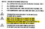
and from 2nd Addendum (S/N >6549)


I don't know if these pictures help or not? I don't have a 250. From this site:
http://amp8.com/tr-amp/marantz/mar250-2.htm


I think I got the order correct on the output transistors: Left side should be PNP pair on top, Right side should be NPN pair on top.From the SM (schematic page 19) S/N 1001-3500:
View attachment 3015624View attachment 3015626
from 1st Addendum (S/N 3501-6509)
View attachment 3015646View attachment 3015647
and from 2nd Addendum (S/N >6549)
View attachment 3015629View attachment 3015630
I don't know if these pictures help or not? I don't have a 250. From this site:
http://amp8.com/tr-amp/marantz/mar250-2.htm
View attachment 3015656
View attachment 3015659
I have a question about the foil side of the amp boards; there is a resistor in the center tied to the bias pot of one of me amp boards, but the other amp board has no resistor underneath the bias pot on the foil side. Should I install this 4.7kΩ resistor on both amp foil sides (R509)?
Im unable to adjust bias on the amp board thats missing the 4.7kΩ resistor, so I'll install the resistor there on the back of the pot to see if anything changes. I was able to safely adjust the other channel bias to 13mV. Both sides DC offset adjusted to about 0 V.I think I got the order correct on the output transistors: Left side should be PNP pair on top, Right side should be NPN pair on top.
I have a question about the foil side of the amp boards; there is a resistor in the center tied to the bias pot of one of me amp boards, but the other amp board has no resistor underneath the bias pot on the foil side. Should I install this 4.7kΩ resistor on both amp foil sides (R509)?
My amp boards revision are AW-115-1071 REV NCThe schematics for that board are different based on the SN and PCB number. Which do you have? Where does the 4.7k resistor connect?
Installed R509 4.7kΩ on left board. This allows me to adjust bias now. Whats the consensus on bias voltage, 13mV?My amp boards revision are AW-115-1071 REV NC
Attachments

Last edited:
I believe the recommended range is 12-15mv make sure to let it warm up and settle I bias at 12mv and seems good

Thanks for the input here from all, I'm going to set it to 13mV after its been on for awhile.An old timer told me to go around 10mv to allow some room to drift.
Tony