• The move to the new server is done. There are some software and database maintenance updates in process. This has us passing the hat around to help out. We appreciate any donations. Seriously, even a dollar helps. The payment page may be found here - https://www.audiokarma.org/support.html

Marantz 2500 Scope P900

Dingle7492

New Member
I have a Marantz 2500 that all seems to work OK, however the Scope is not working. It does have a glow. I went through and tested most of the voltages and am seeing some major discrepancies.

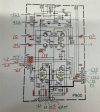
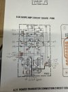
Attached is a photo of the voltage readings. I am new to this, hoping some guru can at least get me started on some specifics to check. I did replace the transistors, 4x SK30's and I replaced the heat shrinked 2SC1507's with new MJE15032G's. Any help would be appreciated!
 

Attachments

  • P900.jpg
    P900.jpg
    98.7 KB · Views: 9
Register to hide this ad
I don't see any 2SC1507s on the schematic or PL. Q905, Q906, Q907, Q908 are shown as 2SC1756. Were those replaced before?

View attachment 3761421
Your Right.. Sorry, just did a 4400. The 4400s have the 2SC1507's. The 2500 have 2SC1756s which I replaced with MJE15032G's @ Q905-Q908.... THANKS! Still struggling with this thing though... Getting ready to start pulling everything and test components. :-(
 
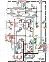
Here is a schematic that I had from before that I annotated to make understanding the function of the circuit a little clearer.
I transferred your voltages onto the schematic (green=good, yellow=?, red=bad).
  1. J914 - All of the input voltages from the P800 board look good.
  2. J901- To JS02 Scope Display Switches
    • AM & FM signal voltages probably vary with the signal input
    • Red dotted line = L channel audio path
    • Green dotted line = R channel audio path
    • Blue dotted line = Multipath signal
    • The bias signals are close so they may be OK
  3. J902 I think that these voltages may change when you rotate the horiz and vertical CRT centering controls so they may not match the schematic?
  4. J912/J913 are the CRT Horiz drive
  5. J910/J911 are the CRT Vertical drive
  6. J903 is basically focus and brightness
  7. J905/J907 goes to the CRT
  8. J904/J904 goes to the CRT
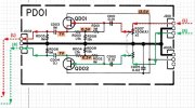
You should be able to check for an audio signal using your scope on J901 connector going into the P900 board. (with Scope ON and Audio button ON)
They should go to the gate of Q902 (L) and Q904 (R).

Screenshot 2026-05-13 132513.jpg
Screenshot 2026-05-13 132909.jpgScreenshot 2026-05-13 133038.jpg
 
Last edited:
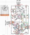
I annotated the diagram a bit more from the schematic to add the CRT interface, brightness and focus, and horiz/vert center controls.
Start debug from J901. Follow the L & R audio signals to Q906 & Q907. Next, make sure that J902 H Center and V Center control are changing voltages as you rotate the controls. EDIT: Added a few more annotations for VRs.

Do you get a bright spot on the CRT screen? Maybe the CRT has gone bad?
Screenshot 2026-05-13 151141.jpg
 
Last edited:
Wow... This is Awesome! Thank You.. The tracing begins... As for the CRT... I don't see a spot, but I am getting a Glow so I am hoping ill be ok once i fix the issues..

I'll keep you posted...
 
Maybe the deflection voltages are incorrect so the spot is off of the screen. When you get a change check the voltages as you rotate the centering controls.
 
Dankik,
After poking around.. Seems like J902, J910, J911, J912, J913 change when adjusting the scope controls, Hor, Vert, Cent... When adjusting all the voltages seem to change smoothly. For example, J912 when adjusting the Horizontal, it can change form 0 to 175v or so. So, the question, is that normal, if so, I am close to assuming that the P900 board itself is good... Any thoughts?
 
I verified that what I am seeing is expected and correct.. So, I am assuming the Board is OK and Voltages are good. Going to start signal tracing stuff...
 
For example, J912 when adjusting the Horizontal, it can change form 0 to 175v or so.
My guess is that the voltage value shown on the schematic is the voltage at roughly the center of rotation of the control. If J912 goes from 0v to 175v, then half-way is 87.5v. The schematic shows 89v so I think that is good. You should see similar action at J913, J911, and J910.

If you have the scope on and position controls centered, and intensity turned up a bit (but not to burn the tube) do you see a dot?
 
Last edited:
So, all voltages seem correct. Getting glow, but no dot. :-( I'm holding out hope that it is something else and not a bad scope! Will Cry.
 
Have you tried to adjust the FOCUS control to see if you get a spot?
You can change the VERT Gain & HORIZ Gain to see if it is too much gain.
If you see a glow, then the CRT is probably OK?
 
Last edited:
I have seen many of the higher voltage rated caps on scope power supply sections be bad. I'd recommend replacing all of the caps in the power supply,
 
Back
Top Bottom