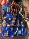
Hi all, so I have been doing some preventative maintenance on my Marantz 250M which seems to work well however I have noticed the left channel has many resistors that test low in circuit compared with the right channel - when tested out of circuit all these resistors measure fine.
what could be causing these resistors to read so differently between the two channel?
This is a very late model board
Each channel has all new transistors which are matched
Some measurements below in circuit left channel vs right
R518 1.03k vs 1.3k
R514 1.65k vs 1.95k
R503 7.2k vs 8.2k
R10 3.6k vs 7.4k
There are others too but this shows the swings which seem pretty significant any ideas??
what could be causing these resistors to read so differently between the two channel?
This is a very late model board
Each channel has all new transistors which are matched
Some measurements below in circuit left channel vs right
R518 1.03k vs 1.3k
R514 1.65k vs 1.95k
R503 7.2k vs 8.2k
R10 3.6k vs 7.4k
There are others too but this shows the swings which seem pretty significant any ideas??