• The move to the new server is done. There are some software and database maintenance updates in process. This has us passing the hat around to help out. We appreciate any donations. Seriously, even a dollar helps. The payment page may be found here - https://www.audiokarma.org/support.html

Marantz 3250 B Transformer

AngelAT

Well-Known Member
Hello AKs,

Recently I bought a Marantz 3250B without knowing what is wrong with her. The seller just said she is defective but did not know what the problem was. Visually the unit was ok, but once I received her and picked her in my hands I had a bad feeling - too light...
So bottomline is I need a power transformer.
Can anyone suggest any other units as donors or specs for a transformer? I checked the usual places online, but with no luck. I found that 3250 uses the same transformer, but still no luck finding.
I live in Europe, so I will need one for 220V - TS16012040.
Any ideas are welcome!
 
Register to hide this ad
Perhaps you could replace the missing transformer with one of the same (or close) physical size. 220VAC primary, and a center tapped secondary of the correct voltage.
Preamps don't draw much power, so a low current transformer would probably work OK.

Tom
 
Hello Tom,

Thank you for the answer!
This makes sense. But I do not know the details - is the secondary 24V?
Can you advise where can I get the info from?
Thanks again!

Angel
 
Your 3250B schematic may provide the voltage on secondary windings. I looked and wasn’t quite sure. if you need it I have a 3250B I can pop cover on and make measurements for you. I can only assume the voltage required on secondary windings will be the same as my 120V unit.
 
  • Like
Reactions: mbz
Thanks!
I would appreciate this - first thing I did was to check the schematics. But I am not sure about the exact figures.
Thanks in advance!

Angel
 
Thanks!
I would appreciate this - first thing I did was to check the schematics. But I am not sure about the exact figures.
Thanks in advance!

Angel
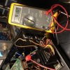
OK Angel, here are your secondary winding AC voltage going to JJ07 across Pin-1 / Pin-3, two orange wires. Ground is Pin-2.
With JJ07 disconnected from board:
Power On: 97.7 VAC
Power Off: 64.5 VAC (probably not relevant, but surprised me when measured after I disconnected with unit plugged in).

With JJ07 Connected to circuit board:
Power On: 91.6 VAC
Power Off: 10.74 VAC

I couldn't say if has to be exact or if a 100V ac secondary transformer will work. Hope this helps.
D71E3A2C-08D8-4F5C-9BFA-E6AB17523910.jpeg
 
Thanks a lot!
I will look for a transformer with a secondary 100VAC.
BTW should I be careful about any other characteristics such as Wattage?
Have a great day!
Angel
 
Last edited:
Thanks a lot!
I will look for a transformer with a secondary 100VAC.
BTW should I be careful about any other characteristics such as Wattage?
Have a great day!
Angel
Your main fuse is only a 1/2 Amp. So I am guessing anything above that that fits? Like Catrafter said, low current draw through PreAmps.
 
A quick update/question

My unit is a (n) type.

I finally managed to get a transformer - input 0-230V, Output 50V, 0V, 50V. The transformer has a total of 6 cables - 3 inputs and 3 outputs.

IMG_20201111_184645.jpg
So far I have never replaced a transformer. For the outputs I think I know where to connect - 0v to J016 between the two orange cables. The other two outputs should go to JP05 and JP07.
My doubt is about the input and this voltage selector switch. Looking at the enclosed diagram I think I should connect one of the inputs to pin 6, the other to pin 1 or 2 and the ground to c of the selector. Is this correct?
OR
Should I go a bit simpler and connect one of the inputs of the transformer to the on/off switch, the other input to the fuse and the third to the ground of the chassis.
One more question, is there any connection between the different inputs and outputs of the transformer? I mean should the input say at the top end (where the fuse is) be matched with the output at the top end (going to JP05)? And if yes, how should I find which end is the top output (as I have said, transformers are new for me...)

What would be your advise?
Thanks!
 
I do not have any experience replacing transformers. Did the transformer come with a schematic or drawing indicating how the inputs should be connected and the voltages of each of the outputs?
 
Thanks for the answer!
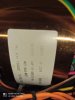
There is no drawing. For the outputs it says 50v, 0v, 50v. Wh-BLK-WH
1605383968987.jpg
I think I know how to connect the outputs. They should go to this small fuse board - at J05 and J07. These are the two 50v leads. The 0 v I think should go to J016 - this is just between the two orange cables, coming from the same small fuse board.
I can also connect the two inputs, based on the schematic.
My only concern is should I connect the green/yellow (n) of the inputs to ground on the chassis or leave it unconnected...
 
I'm sorry I don't have an answer for that. Try and follow the schematic I guess. I don't see a ground on the input side of the schematic. Just Hot and Neutral. Is the label indicating N: Grn/Yel is the Neutral wire? Unfortunately I'm stuck fighting with a dial cord string on a 4240 and I don't have time to look at my 3250B until that is resolved.
 
Is the label indicating N: Grn/Yel is the Neutral wire?
Yes, this is what is written on the Transformer.
Unfortunately I'm stuck fighting with a dial cord string on a 4240 and I don't have time to look at my 3250B until that is resolved
I have done dial cords and I used isolation tape to hold it to the wheels. But not too tight, so that it can move. Hope this might help you. I am not sure if you can get the info from your 3250B, because what I saw from your picture yours is the US model and does not have the voltage selector switch.
But, anyways, if you find any info, I will be grateful. And I am not in a hurry - currently working also on a 2265B and a 2235 which I acquired recently.
Good luck with the cord!
 
Finally got the dial cord done. The guide in SM is a little ambiguous. Definitely using tape. The trick seemed to connect to the string on the middle of the loops around drum (5) instead of immediately (4) as is shown in the blow up of the drum. If hook to spring on first turn the drum binds moving across the dial at about 1/2 way.
 
A quick update!

Finally I found the time to finish this beauty.
Installed the new power transformer, recapped the whole unit and replaced a gone zener and a wrong value transistor. All pots and switches cleaned. And all is perfect!
Btw still have a strange feeling about the way this unit is connected...
...and cannot find an owner manual online.

One more project finished and one more Marantz saved!

IMG_20201205_222723.jpg IMG_20201205_222711.jpg IMG_20201205_222641.jpg
 
Back
Top Bottom