• The move to the new server is done. There are some software and database maintenance updates in process. This has us passing the hat around to help out. We appreciate any donations. Seriously, even a dollar helps. The payment page may be found here - https://www.audiokarma.org/support.html

Marantz 4300 Partial-Rebuild thread

goldswimmerb

Failed out of engineering, but look at me now!
Subscriber
Hey guys, so as many of you have been aware I have been working on a 4300 (or two) for the last few months. Its been and adventure and a learning experience, and I am extremely grateful for the wonderful help I have received from various forum members. I figured Id keep making new rebuild threads when I get things o that I am not a "taker" from this site, but also a giver. Without the information found here, none of my work would even be possible.

This 4300 was given to me for a partial restoration/tune-up, and I had no clue what mess I was originally getting into, should have just immediately returned it to the guy, you can see my original thread for the details there. The first one had a ton of questionable work and after fiddling for a few weeks, and one small tragedy, I had relegated it to a parts unit and managed to acquire another in a moderately less molested state. I'm actually taking a pretty huge loss on this servicing money-wise, so some things (like the filter caps, dolby board and tuner) are being left out to save me a bit.

The original one wound up befalling a tragedy, at my fault, ultimately costing me around $400 and a whole lot of time/parts, since after breaking one of the pushbutton boards and several buttons the original unit was no longer worth the time or the effort to repair (in addition to many other issues it already had). Essentially split the price of the new one, and am doing a partial rebuild and addressing areas of concern/potential reliability issues.

So far I've gone and done the main amp boards, preamp and tone board, and the PSU. Going to do the phono board, Vari-Matrix and Phase inverter and the call it done, for my sanity and time's sake.

So far I noticed both of the amps had work done on the main amp boards, I used the two boards that were closest to original and didnt show signs of abuse by extremely bad servicing, had to toss both amp boards from the replacement amp as one was using the wrong driver transistors (probably fine), one had the D357 transistor replaced and there were a few other small issues here and there. The other amp just had most of its small-signal transistors in the amp board replaced, looking the replacements up the proper ones were used, so I decided to use those two amp boards.

Both amps also had work done on the PE01 board, the first one just had random components popped in (no joke found transistors in places they shouldnt be) and the 2nd one actually had proper replacements for a few.
Original amp even had mismatched filter caps...


Ill be updating this thread as I get to it, there's a lot to post...
 
Register to hide this ad
So I figured I would get the worst out of the way first.
I started with PE01 and PD01. The PE01 board caused the most trouble due to its positioning and wiring. I found the easiest way to get under the board was to remove the ground wires (I hate the ground scheme here, near impossible to make it look clean) and desolder the wires going from PE01 to PD01 on the PD01 side. Doing so allowed relatively easy access to the bottom of the board.

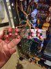
Finished PE01 Board (didn't get a good close up):
IMG_20191106_205815.jpg
Wires are still a mess as I'm yet to clean them up. After servicing I had actually lost one of my channels so I went back and reflowed the solder joints in the affected area.

Doing so got me mostly there, the next day I actually noticed the channel would drop out when the amp was rotated onto its feet, weird that it would work on its side and upside down but not in its proper orientation. I'm still not entirely sure what was causing this, however rearranging the wires, pulling on the PE01 PCB a bit and retightening the screws seems to have done a trick, not sure if its a crappy solder or a pinched wire. After doing that I then noticed that if I apply pressure to the chassis frame towards the center I get a pretty significant pop through the speakers, guessing its probably a ground thing, but I don't see it causing an issue when the amp is assembled given there's no way to cause the issue without sticking your hands where they don't need to go. I may chase the issue down a bit more but I'd say its a non-issue.

The parts I used in the PE01 board were:

Disclaimer: Most of thee are from memory and going back over my orders, I keep so many caps and other parts stocked that I can't always remember what I put in, may have mixed some mouser number up between capacitor physical sizing as well.

CE05-CE08 Nichicon UKZ 22UF 50v - 647-UKZ1H220MPM
CE09-CE12 WIMA MKS2 2.2UF 63V - 505-MKS2C042201K00JO
(The WIMAs were a little big for the positions on this board, probably should have gone with a different series, I know I used to have smaller sized 2.2UF but can't remember what WIMA series it was)
CE13-16 WIMA MKS2 4.7UF 50V - 505-MKS2B044701K00JS
CE17-20 Nichicon UPW 47UF 50v - 647-UPW1H470MED1TD
CE21,22 Nichicon UPW 220UF 50v - 647-UPW1H221MPD6

HE21-24 2x 1N4148 in series - 512-1N4148
HE01 - HE04 KSC1845FTA - 512-KSC1845FTA
HE05 - HE08 KSA1013YTA - 512-KSA1013YTA
HE09 - HE12 KSC2383YTA - 512-KSC2383YTA
HE13 - HE16 KSC1845FTA - 512-KSC1845FTA

HE17-HE20 - Left original as the 2SA763 hasn't caused me any problems yet, and the more I change the more likely I am to make a mistake...

I'm still learning so please don't hesitate to call me out for using an ill-suited transistor or capacitor!

PD01 will get its own post when I have a chance.
 
Now onto PD-01, this board is a strange one, held on mostly by solder and a single ground screw, and the most fragile traces I have ever seen. Its also got several 2SC1345 transistors, which I always replace as a precaution. I did actually swap the 2SA763s here as well, but I've since decided to stop doing since I'm yet to have a 763 cause me any trouble. Board originally comes with several BP 'lytic caps and a few tantalums.

Lots of WIMA films here, made me realize I really need to get the part number for the smaller sized ones since I know they exist.

Anyway,
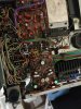
Board picture:
IMG_20190911_212747.jpg
CD01 - CD04 1uF WIMA MKS2 50V - 505-MKS2C041001F00JA
CD05 - CD08 3.3UF WIMA MKS2 50V - 505-MKS2B043301H00KI
CD09 - CD12 4.7 UF WIMA MKS2 50V - 505-MKS2B044701K00JS (may have gone 63v here, cannot remember I order a bunch of these)

HD01 - HD04 KSC1845FTA - 512-KSC1845FTA
HD05 - HD08 KSA992FBU - 512-KSA992FBU
 
These are a pile of work! The worst 4 channel receiver for me has been a small one, the model 4220. Way tooo much in the small chassis size.
 
These are a pile of work! The worst 4 channel receiver for me has been a small one, the model 4220. Way tooo much in the small chassis size.

This one has been a learning experience for sure. Figured 2x the channels 2x the complexity, instead, I got 2x the channels 8x the complexity and 10x the VD1212s and other failure-prone semiconductors :')
 
I agree with both of you!
The 4300/4400s are difficult due to the size/complexity, the 4220 due to it's fragile boards and the double sided balance control board with intermittent 'griplets'.

None of the quads are all that easy, but I still love 'em.

Tom
 
Alright, so I just did the phono board tonight, I did it as per the standard around here for P700/P400 boards so I'm not going to list off all the mouser numbers for this one.

IMG_20191113_222551.jpg

CE401 and 402 Became 1UF 50V WIMAs like I've been using elsewhere.
CE403 and 404 became Nichicon UES 47 UF 25V (original ones were 47UF 25v polar caps)
CE413 became a 270UF 50V Nichicon UHE I had since it was low profile enough to fit.
CE414 and CE415 Became my typical 1UF WIMAs*

VD1212 replaced with 2x 1N4148 diodes in series, replaced the other two diodes with single 1N4148s.

The tranistors on this one were something I was/am experimenting with, as I have heard reports of KSC1845s causing oscillations when used in placed of the 2sc1344s here.

I replaced the 2sc458s with KSC1845s.
Initially I replaced all of my 2SC1344s with KSC1845s but noticed my right speaker driver bouncing like crazy (my cable was also crap).

As a test I swapped H401 and H402 over to KSC1815s, seemed to solve the issue but I'll have to test more, I think the KSC1815s may go better in H403 and H404 positions as the service manual mentions the D suffix for the 1344s as an option which would put the 1815s within reason as far as HfE is concerned. Though I'm not certain how much it matters. Perhaps someone with more expertise could weigh in here...

I also noticed that CE403 and CE404 seem act a bit odd, if I touch something to the top of the cap while it's on I'll get a loud pop in the corresponding speaker, not sure what's up there...

Also, is there a reason for CE414 and CE415 to be 250V? I don't see a reason for there to ever be that much voltage there.
 
Alright, onto the amp boards. I had originally intended to add flyback diodes, however, I ran into some, uhhhh issues...

I had added some flyback diodes for protection based off of the drawing catrafter was nice enough to supply for me, it worked at first, however, I think either a bad diode or space limitations got the best of me. Initial test after installing diodes was good, everything worked as expected on the DBT, then I installed the amp shield and tested again, got an extremely nice sizzle and smoke from the amp with diodes, pulled the board to two shorted output transistors, a split diode and several other shorted transistors. I would up just rebuilding a spare board/outputs I had on hand from a 4300 that someone else had completely butchered as I wasn't in the mood to tear the whole thing apart to find however many transistors or diodes I blew up.

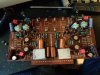
Anyway, here's the rebuilt board (took this before I replaced the 2sc458s):
IMG_20191109_172953.jpg
Went with 220uF 50V UPW caps for the axial caps, used some creative lead bending.
WIMA films for the 2.2uF tantalums.
Nichicon UKZ for the two 25v 47 UF capacitors, and replaced the .68uF electrolytics with a combination of WIMA films (.22uF and .47UF 10%) as I dont keep .68uF films in stock since they're not seen often.

Replaced the 10uF capacitor in parallel with the VD1212 diode on the bias circuit with a 10uF UFG. VD1212s were replaced with 2x 1N4148 diodes and the 2sc458s (at least in this board) got swapped to KSC1845.

The other board got the same treatment until I blew it up... After blowing it up I moved the new parts from the blown board over to a spare amp board I had that was only partially butchered by someone else. Some bozo had decided to solder the screws holding the 2SD and 2SB diodes in place, so I was unable to change out the 2sc458s. I've decided to (gasps and cries) leave them in for the time being. Ive told the guy I'm fixing it for that there may still be some failure-prone transistors in one channel, and if they cause issues down the line he's local so I'll just go and deal with them then. I've had this amp on the bench for 3 months now and just need it gone.

Luckily the amp boards are the easiest to work on in this amp thanks to being slotted so I have no problem replacing the 2SC458s in the future, just have no desire to do it now.
 
Since today is pretty slow, I'm going to get another board squeezed in here. The PS board. I went all out on this one since I've noticed that the PS and Preamp tend to make the largest difference in sound, whereas the main amp is mostly upgraded/recapped (in my experience) for reliability.

What was done here:
Replaced DS-131 Dual Diodes with MUR1620 devices (overkill but whatever)
Replaced the Two TO-66 dual diodes that are the rectifier with MUR1620 devices
Replaced all capacitors, moved the 1000UF cap from chassis mount to board mount
Replaced the 2SD331 transistors with MJE15030 transistors.
Replaced the hot running 150ohm 5w cement wire-wound resistor with a 7w enamel wirewound resistor and raised it up off the board for proper cooling.
Someone had previously replaced the 2SC1318s here so no need to worry about those.

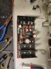
Board Pics:
IMG_20191112_001051.jpg

Parts list: All caps are of same of higher voltage rating (list based off SM)

Caps:
C804 470UF 63V - UPW2A471MHD
C805 220UF 50V - 647-UPW1H221MPD6
C807 10UF 50V - 647-UFG1H100MDM
C808 220UF 50V - 647-UPW1H221MPD6
C809 470UF 16V - 647-UPW1H471MHD
C812 22UF 63V -647-UPW2A220MPD1TD
C813 47UF 16V - 647-UPW1E470MDD1TA
C814 220UF 10V - 647-UPW1E221MPD1TA
Chassis mount (unsure of number) - Repaced with 1000UF 63V - 647-UPW2A102MHD
Resistors:
R809 150 Ohm 5W - 66-W221500JRLF
Semiconductors:
H801, H804 2SD331 - 863-MJE15030G
H810, H811 DS-131B - 863-MUR1620CTG
H812 1S-2725 (S) - 863-MUR1620CTG
H813 1S-2725 (R) - 863-MUR1620CTRG

Fitting in the TO-220 devices in place of TO-66 isn't always pretty, but it worked out pretty well this time imo.
 
i feel your pain. somebody just plopped down one of these monsters onto my bench. had to undo 4,897 screws just to get the last bolt off the power transistors,

what are you using for the 2SC1403 and 2SA745 pw transistors? i did not see anything in the cross ref pdf on file here.

drivers also, what used for the B527 and D357?

i have a replaced 100 ohm with burnt on the board , 4 of the pwr transistors are blowm, i guess use MJ21193/4 ?

thanks for all your hard work!
 
i feel your pain. somebody just plopped down one of these monsters onto my bench. had to undo 4,897 screws just to get the last bolt off the power transistors,

what are you using for the 2SC1403 and 2SA745 pw transistors? i did not see anything in the cross ref pdf on file here.

drivers also, what used for the B527 and D357?

i have a replaced 100 ohm with burnt on the board , 4 of the pwr transistors are blowm, i guess use MJ21193/4 ?

thanks for all your hard work!

Not certain for the power/driver transistors, but I would guess MJ21193/4 should be okay for outputs. I happened to have a box of originals pulled from a parts amp.
 
we will try

H713, H715 > KSC2073 150 V 1.5 A hfe 40-140 NPN

H714, H716 > KSA940 - 150 -1.5 A hfe 40-140 PNP

for the drivers, 4 ea required.

FYI 2SC1403 and 2SA745 pulled from good channels measure out at 40 to 45 hfe (gain) @ 450 -ma, 4 V=ec

MJ21193/4 usually have higher gain so keep an eye out for osc. problems which may require additional capacitance added somewhere, like B to C,
 
Last edited:
Back
Top Bottom