

You are using an out of date browser. It may not display this or other websites correctly.
You should upgrade or use an alternative browser.
You should upgrade or use an alternative browser.
Marantz 6300 Project
- Thread starter Echoplex
- Start date

mlannoo
New Member
Marantz 6300 Project Part 2
I made quite a bit of progress this weekend.
First, I got started desoldering the old caps with the Hakko 808, then cleaned off the glue from the old caps with Acetone and a gillion Q-tips. Thanks Marantz!Next, I recapped the power supply with Panasonic FM 105 degree caps and replaced all of the resistors with Ohmite OD Little Demons (carbon composition types); these are low noise, high temp & rapid heat dissipation. I think it turned out pretty good!
Power Supply with new electrolytic caps, new carbon comp resistors and new SCR from ON-Semi. Most of the wire wrap connections on the pin lugs were redone as well.

Speaking of wire wrap...the 24 awg wire is very delicate. One little twist on the board the wrong way, and snap, you'll have to do it over again. I've gotten quite a lot of practice during this project.
After finishing the power supply board, I got started recapping the motor. I used Nichicon HE & MV series 105 degree caps with the same capacitance/voltage specs as the originals. As you can see, these are quite a bit smaller than the original ones, but they fit perfectly. If you have this particular motor version, just remember to be very careful with the soldering iron. I would suggest doing one component at a time.


Jonard (HW-UW-224) wire wrap/unwrap tool. Life saver right here, although a little pricey.

All in all, everything has come out good so far, but it has been a lot of work doing this project, including researching all of the component replacements, re-doing the wire wrap connections (several times) and jumping over the unexpected hurdles along the way. Thank goodness I had a spare parts 5020 deck laying around because I've used a lot of wire from it to run new wire connections on this project.
Hope other 6300 owners are finding this thread useful and enjoyable.
To be continued...
Thanks for contributing with this post on the 6300. I picked up one myself a few months ago and I recapped the power supply and put an Ortofon 2M blue cartridge on. I'm pleased with the sound but am still a little disappointed in the turntable's motor "strength" - was wondering if replacing the electrolytic caps on the motor might help that? Any other things to consider that might make this TT platter start "stronger"? Or am I just spoiled from having a Technics 1200 for so many years? Thanks.

Echoplex
Active Member
Thanks for contributing with this post on the 6300. I picked up one myself a few months ago and I recapped the power supply and put an Ortofon 2M blue cartridge on. I'm pleased with the sound but am still a little disappointed in the turntable's motor "strength" - was wondering if replacing the electrolytic caps on the motor might help that? Any other things to consider that might make this TT platter start "stronger"? Or am I just spoiled from having a Technics 1200 for so many years? Thanks.
You're spot on with your analysis. The "motor strength" on the 6300 does indeed have weak torque - especially on initial start-up and after stylus drop. I doubt that you'll notice any measurable improvements after putting in new electrolytics in the motor. Mine still drifts a little, and I have to tweak the pots to get it to settle in at first, but once I run it for awhile it stays steady. I assume the initial speed drift is due to the cold temperature on the drive coil transistors and oscillator, but as it warms up it settles down.
Unfortunately, the 6300 motor did not have a quartz lock design feature like the 1200. The quartz crystal, if i understand the theory correctly, offers more stability regardless of temperature. Still, even with all of it's flaws, I still enjoy mine. Good Luck!
Last edited:
This is a great thread with lots of useful information, I would like to profusely thank all you contributors. Unfortunately, I can't add to that, but I am just looking for an opinion or answer.
I am currently trying to get one of these 6300's running for a relative, have freed up the motor and recapped the power supply, looks like I need to replace a switch (S006, won't reliably open), and fix an open in the right channel signal RCA cabling out (apparently open right at the support on the TT). Not a quality restoration, just enough to get it running so the relative can use it and I have found this thread to be exceedingly useful. The unit I am working on has an IC motor dated 24Nov76. I may not be able to fix the cue up/down function, although I have an SCR on the way.
I do have a couple of questions, regarding this TT, namely R808 & R809, involved in the photo-transistor/SCR circuit. My electrical circuit knowledge is limited and I have found that on this TT R808 is actually 1500 Ohm (brown green red) versus the schematic shown 1K, and R809 is 10k (brown black orange) versus the schematic shown 15K (these are the original resistors). Overall my thoughts are that these changes from the schematic would put more current through the photo transistor, and maybe provide better damping and gate voltage build up on the H805 SCR. Any idea why they would make these changes or are my guesses any good? Maybe this was the result of lessons learned over the production cycle regarding better function and related component life? Or maybe on that day they just ran out of the normally installed resistors and these were "close enough"?
I am currently trying to get one of these 6300's running for a relative, have freed up the motor and recapped the power supply, looks like I need to replace a switch (S006, won't reliably open), and fix an open in the right channel signal RCA cabling out (apparently open right at the support on the TT). Not a quality restoration, just enough to get it running so the relative can use it and I have found this thread to be exceedingly useful. The unit I am working on has an IC motor dated 24Nov76. I may not be able to fix the cue up/down function, although I have an SCR on the way.
I do have a couple of questions, regarding this TT, namely R808 & R809, involved in the photo-transistor/SCR circuit. My electrical circuit knowledge is limited and I have found that on this TT R808 is actually 1500 Ohm (brown green red) versus the schematic shown 1K, and R809 is 10k (brown black orange) versus the schematic shown 15K (these are the original resistors). Overall my thoughts are that these changes from the schematic would put more current through the photo transistor, and maybe provide better damping and gate voltage build up on the H805 SCR. Any idea why they would make these changes or are my guesses any good? Maybe this was the result of lessons learned over the production cycle regarding better function and related component life? Or maybe on that day they just ran out of the normally installed resistors and these were "close enough"?
This is a great thread with lots of useful information, I would like to profusely thank all you contributors. Unfortunately, I can't add to that, but I am just looking for an opinion or answer.
I am currently trying to get one of these 6300's running for a relative, have freed up the motor and recapped the power supply, looks like I need to replace a switch (S006, won't reliably open), and fix an open in the right channel signal RCA cabling out (apparently open right at the support on the TT). Not a quality restoration, just enough to get it running so the relative can use it and I have found this thread to be exceedingly useful. The unit I am working on has an IC motor dated 24Nov76. I may not be able to fix the cue up/down function, although I have an SCR on the way.
I do have a couple of questions, regarding this TT, namely R808 & R809, involved in the photo-transistor/SCR circuit. My electrical circuit knowledge is limited and I have found that on this TT R808 is actually 1500 Ohm (brown green red) versus the schematic shown 1K, and R809 is 10k (brown black orange) versus the schematic shown 15K (these are the original resistors). Overall my thoughts are that these changes from the schematic would put more current through the photo transistor, and maybe provide better damping and gate voltage build up on the H805 SCR. Any idea why they would make these changes or are my guesses any good? Maybe this was the result of lessons learned over the production cycle regarding better function and related component life? Or maybe on that day they just ran out of the normally installed resistors and these were "close enough"?
To update my own questions, I determined that my power supply is a different version than what I have found in the service manuals and in this thread. In addition to the differing resister values noted above, it has a C806 470microfarad, 50V electrolytic across J807 and J813. There is no J810. Other than those minor differences, with the proper gate voltage SCR and Darlington photo transistor (both as mentioned earlier in this thread) everything else is much the same and works fine. The part number on the board I have is YD2939001 - 2 (ELNA-F45 94V-1)


Marantz 6300 upgrades/modifications
FWIW, to those who are tuning into this thread, I am going to be undertaking and documenting a Marantz 6300 project in finite detail within the next few weeks. I'm waiting on new parts and shipments to arrive, hence the delay.
My overall plan with the project is to post detailed photos, procedures I used, list the parts and provide an updated wiring schematic for the US/Canada models. My apologies to the international folks. To my knowledge, there are currently three different schematics that are in regular circulation on the web. Problem is, all three of them have minor mistakes on them, and the two US versions have different tonearm wiring diagrams, making it even more confusing for the newbies like me. HA!
I will also be including detailed photos of the Auto Mode/Photo Unit (H002) circuit and where to find replacement parts for it etc. FYI - the service manual has a pretty thorough explanation into the circuits operation and provides part numbers, although they're old and outdated, so new component replacements will be helpful for those looking for answers. I've seen many threads on the web asking how to fix and/or adjust this, so thought I'd include it as well.
This is going to be a lengthy project, but hopefully, will benefit those wanting to learn more about the 6300's internals and perhaps give them some ideas on how to approach it and in the end, make it sing! I do hope that lots of folks here will contribute to this project and share their insight as well, with the end-goal of the thread becoming a sticky, so everyone can get the answers they need.
6300 Project Detail:
- Rewire tonearm using Cardas/Litz OFC .33 awg
- Dampen the tonearm internally using cotton sleeve
- Install new custom RCA jack plate on back for removeable IC's
- Install new Sumiko HS-12 Headshell w/litz leads (**)
- Install new strobe light and resistor
- Provide new wiring schematic (USA/Canada model)
- Provide auto mode operation (possibly via video), adjustment and fixes etc.
- Document & photograph all procedures used
(**) HS-12 has adjustable azimuth, is slightly lighter than original headshell, and is also non-resonant. The result: better soundstage, less weight, less wear and tear on your records and more adjustment features = happy record owner and longer lasting records.
By the way...
I'm doing this project because I have micro-switches and tonearm wire that need serious attention due to the previous owner taking liberties where they probably shouldn't of, so that said, a modification is in order.
Also, I'm not suggesting for a nanosecond that current 6300 owners should try or attempt to mod/tweak their equipment in any way. Like most of you, I'm here to learn and understand the science behind the circuits operating parameters and share with you what I find, as well as, learn from all of you too! However, if you're happy with your equipment the way it is, then by all means keep it that way.
Lastly, I'd like to say that the community here @ AK is truly an awesome place to come and hang out and learn about audio. There are a ton of talented folks here lurking and posting all of the time. No joke. I'm amazed by their knowledge and know-how of electronics. I've learned way more here than I have studying circuits in school, so thankyou for that! :thmbsp:
OK, I've written a novel. Sorry bout that...
Stay tuned...

nothing against the brand, but the 6300 is not worth upgrading its just a mid grade table built by some company in Japan for them. I’ve fixed a few of these and I know their shortcomings, I even had armless model and I dropped an SME 3009 and tried a Rega RB300. What I’m saying even if you spend $$$$ on a fancy arm, wires and cartridges, you cannot improve its wow and flutter and rumble specs which are mediocre to begin with. The build is so so imho, wood screws to mount the feet, to the plinth, they could have used treaded inserts to make it robust, but you end up putting Elmer’s wood filler or glue on the screw holes to make them hold, those feet are crap to begin with they are feedback amplifier. I did mods in the plinth and the platter added some Dynamat sound absorbing pads used on auto ice sound systems and bought some better feet like oreal, sorbothane or isotone types. Another good one a a really good isolation board under the table. The factory arm is not even mid grade it’s a very common arm found on a lot of Japanese tables. Every time I get a 6300/6320 I just service and calibrate and sell it quickly coz Marantz freaks snap them up quickly and use the profits to further upgrade my sound system like investing more in really good speakers, definitely not anything made by Marantz.
If you hell bent on keeping your 6300/6320, I’d say splurge more on and get really higher end
Tonearm and a decent cart. I’d rather just use all the money on a Thorens td125 with an sme arm, Linn LP12, Mitchell or even a Technics SP10/15/25 ir SL1200GR/G, Rega, VPI, Oracle etc….just my 02 cents.
Hi
Had my 6300 in for maintenance but techs don't want spend time on old equipment to fault find and order replacement parts these days - too difficult and time better spent in selling a new TT at $1500
So I have ordered parts from moser to attempt the rework myself
The 6300 is working ok in manual mode, but in auto, the photo unit (H002) is a random response to the beam being cut by the tonearm shield, either the red led or the darlington may be at fault..
Question 1 If manual mode is ok, can I assume all switches are ok ? ---- but I have ordered 2 just in case.
Question 2 Before I start changing components, is there any particular order like Red LED first and then test?
Question 3 Any mistakes to avoid like putting a new component the wrong way or are the components self explanatory and a correct placement is obvious?
Parts list -
Mouser Part # 653 - VX-5-1A3 (Omron Miniature Basic Switch)
Mouser Part # 710 - 860160672001 (Wurth Electrolytic Cap)
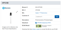
Mouser part # 828 - OP535B (Optek Photo darlington)
Mouser Part # 859 - LTL-4222N (Lite-on Red Led)
Mouser Part # 863 - MCR72-3G (Littelfuse Thyristor)
Plus the 5 main caps at c801 to 805
From the 6300 project - Seems a change of the H002 components may help get the auto mode working.
I hope someone can set me straight and thank I you in advance
Had my 6300 in for maintenance but techs don't want spend time on old equipment to fault find and order replacement parts these days - too difficult and time better spent in selling a new TT at $1500
So I have ordered parts from moser to attempt the rework myself
The 6300 is working ok in manual mode, but in auto, the photo unit (H002) is a random response to the beam being cut by the tonearm shield, either the red led or the darlington may be at fault..
Question 1 If manual mode is ok, can I assume all switches are ok ? ---- but I have ordered 2 just in case.
Question 2 Before I start changing components, is there any particular order like Red LED first and then test?
Question 3 Any mistakes to avoid like putting a new component the wrong way or are the components self explanatory and a correct placement is obvious?
Parts list -
Mouser Part # 653 - VX-5-1A3 (Omron Miniature Basic Switch)
Mouser Part # 710 - 860160672001 (Wurth Electrolytic Cap)
Mouser part # 828 - OP535B (Optek Photo darlington)
Mouser Part # 859 - LTL-4222N (Lite-on Red Led)
Mouser Part # 863 - MCR72-3G (Littelfuse Thyristor)
Plus the 5 main caps at c801 to 805
From the 6300 project - Seems a change of the H002 components may help get the auto mode working.
I hope someone can set me straight and thank I you in advance

MarantzRefrb
Super Member
Hi
Had my 6300 in for maintenance but techs don't want spend time on old equipment to fault find and order replacement parts these days - too difficult and time better spent in selling a new TT at $1500
So I have ordered parts from moser to attempt the rework myself
The 6300 is working ok in manual mode, but in auto, the photo unit (H002) is a random response to the beam being cut by the tonearm shield, either the red led or the darlington may be at fault..
Question 1 If manual mode is ok, can I assume all switches are ok ? ---- but I have ordered 2 just in case.
Question 2 Before I start changing components, is there any particular order like Red LED first and then test?
Question 3 Any mistakes to avoid like putting a new component the wrong way or are the components self explanatory and a correct placement is obvious?
Parts list -
Mouser Part # 653 - VX-5-1A3 (Omron Miniature Basic Switch)
Mouser Part # 710 - 860160672001 (Wurth Electrolytic Cap)
Mouser part # 828 - OP535B (Optek Photo darlington)
Mouser Part # 859 - LTL-4222N (Lite-on Red Led)
Mouser Part # 863 - MCR72-3G (Littelfuse Thyristor)
Plus the 5 main caps at c801 to 805
From the 6300 project - Seems a change of the H002 components may help get the auto mode working.
I hope someone can set me straight and thank I you in advance
I had a bit of a different problem with Auto Mode, but here were my troubleshooting steps:
https://audiokarma.org/forums/index.php?threads/marantz-6300-tt-auto-mode-not-working.994549/
If you have a solid red LED when you look under there, the problem likely isn't the LED, the LED would need to flicker, or go out in order to be the cause of the intermittent Auto Mode operation.
You could take a meter and test the voltage of the photo receiver side, when open, and closed. I used a guitar pick to close the photo receiver side manually (behave like tone arm actuator), in order to get an accurate reading and determine the photo receiver was working correctly. IIRC the voltage was 18V closed, and about 5V open, that might be backwards.
What can also happen is that one of the physical switches is out of alignment with the mechanical levers, and is not fully opening, or closing, when it should be, and causing intermittent function.
Thank you for the info - I now have all the parts. I am awaiting on a MESR-100 in circuit cap tester before I look at the caps (c805 may be an issue)
My action plan is to check for glow from the red led - if ok, check voltage and perhaps replace the darlington -- but why not just replace both led and transistor and then check s002 then s005 and s003. switch s6007 cue-up is working ok.
I dont know if my 6300 has a ball bearing in the motor shaft and if so it's diameter and the internal shaft measure. If no ball- I have a small bearing set from a computer disk drive (6, 1ml balls in a 7.5ml external diameter circle/frame which may fit at the bottom of the shaft - maybe if it is not less than 7.55 ml in dia.
My action plan is to check for glow from the red led - if ok, check voltage and perhaps replace the darlington -- but why not just replace both led and transistor and then check s002 then s005 and s003. switch s6007 cue-up is working ok.
I dont know if my 6300 has a ball bearing in the motor shaft and if so it's diameter and the internal shaft measure. If no ball- I have a small bearing set from a computer disk drive (6, 1ml balls in a 7.5ml external diameter circle/frame which may fit at the bottom of the shaft - maybe if it is not less than 7.55 ml in dia.
Caps all OK, so no change
Glow from red led, so Is OK
Changed photo transistor next in line - tttable now turns off at record end and raises arm, so is OK
Reset motor pitch for 45 speed which was at hard minus at top pitch control so speed is stable.
All switches are OK
Marantz 6300 now OK and working like it was new.
A few spare bits left - maybe for fixing new failed bits before I cark it.
Interesting that no hifi repair trades have time to understand 70's/80's equipment. I guess, that means latest very expensive gear is doomed for the scrap heap when it fails. As well as the old inexpensive gear.
Many Thanks to those on this site who have devoted time, shown photos and given fixit tips.
.
Glow from red led, so Is OK
Changed photo transistor next in line - tttable now turns off at record end and raises arm, so is OK
Reset motor pitch for 45 speed which was at hard minus at top pitch control so speed is stable.
All switches are OK
Marantz 6300 now OK and working like it was new.
A few spare bits left - maybe for fixing new failed bits before I cark it.
Interesting that no hifi repair trades have time to understand 70's/80's equipment. I guess, that means latest very expensive gear is doomed for the scrap heap when it fails. As well as the old inexpensive gear.
Many Thanks to those on this site who have devoted time, shown photos and given fixit tips.
.

bfalchi
New Member
Great info. I'm having a auto shutoff issue, checked voltages at photo unit, OK and LED is bright red in auto and manual, deoxit All switches. What I have troubleshooted so far is when in Auto and the record reaches the end it does not pop up and shutoff, but when I move the tonearm across the record, in Auto mode, at the end of the record it will pop up and shutoff? So I'm thinking replace the phototransistor? Has anyone had this issue with their 6300 auto shutoff? Thoughts
MarantzRefrb
Super Member
Great info. I'm having a auto shutoff issue, checked voltages at photo unit, OK and LED is bright red in auto and manual, deoxit All switches. What I have troubleshooted so far is when in Auto and the record reaches the end it does not pop up and shutoff, but when I move the tonearm across the record, in Auto mode, at the end of the record it will pop up and shutoff? So I'm thinking replace the phototransistor? Has anyone had this issue with their 6300 auto shutoff? Thoughts
That you are able to get the tonearm to manually trigger the Auto-shutoff, and make the solenoid engage and lift the tonearm, would mean you're mostly in good shape.
What it sounds like to me is your photo-transitor unit needs to be adjusted, or moved closer or farther from the tonearm actuator, to set the Auto-off trigger at the spot you want it to pick up the arm.
There is a small port/hole in the back of your 6300 with a screw head on it, that's the photo-transistor adjustment, you can turn that to move the unit to the correct trigger spot.

bfalchi
New Member
What it sounds like to me is your photo-transitor unit needs to be adjusted, or moved closer or farther from the tonearm actuator, to set the Auto-off trigger at the spot you want it to pick up the arm.
I tried that multiple times and still no luck. I also removed the bottom cover and in auto mode I moved a guitar pick in between the LED and Phototransistor, when i moved the guitar pick between both fast, it kicked off and then i moved the guitar pick slow between both as if the record was playing , it would not kick off? strange
bfalchi
New Member
That's the plan. Ordered a replacement phototransistor from Mouser. Thanks and I'll let u all now how I make out after I receive and install.If all works in Manual mode and if switches 002 and 004 test Ok and if LED always glows red then Darlington transistor in PH101 likely needs replacing
bfalchi
New Member
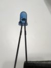
Sorry, I read the data sheet and I'm good now, flat part on Photo transistor component, not pinsHey all, just received 2 photo transistors and I am aware that terminal 1 (on the mini-pcb) receives the collector (component flat side) and terminal 2 receives the emitter, but is it me or per the photo both pins are flat? just trying to make sure I install correctly. Thanks

Attachments
bfalchi
New Member
That's the plan. Ordered a replacement phototransistor from Mouser. Thanks and I'll let u all now how I make out after I receive and install.
Hey all, Just installed a new photo transistor and that fixed my issue, works like a charm now. thanks for the guidance. Ben