Lee Hester
New Member
Hi,
I've had a lot of MA-700 monoblocks over the years and they always eventually succumb to intermittent popping. This seems to be a common issue.
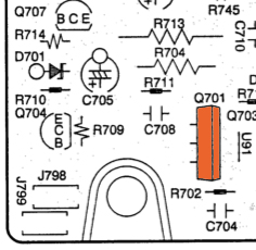
This area of the P701 circuit board tends to get a charred look:
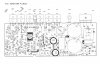
Here is the whole board layout:
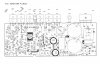
Here is a schematic of the whole circuit board:
Many people say that replacing Q701, Q702, Q703, Q704, Q705, Q706, Q707, Q708, Q722 & Q723 fixes the issue. Some replaced resistors in the area. One person had problems replacing Q701, as the replacement part did not work and had to be replaced by the old part.
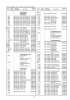
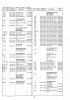
Parts lists:
I am not an electrical engineer, nor do I play one on TV. But I can wield a soldering iron. I know some of the DIY folks here are incredibly capable and know MUCH more than I ever will about these items.
SO
1. Are there alternative versions of any of the parts listed as needing replacement that would be better at handling the heat, or just generally a better replacement?
2. Where would you suggest I source these parts?
3. Should I replace the resistors in that area? If so, is there some "upgrade" that would better dissipate heat?
and
4. In generally refurbishing this amp, people say changing out some capacitors can REALLY boost performance. Anyone with such experience on this amp? What caps (besides just the bad ones) would you replace and what brand(s) would be a good "bang for the buck"?
5. After doing all this work, one person remarked, "As I read the print, those transistors, using the zener D705, provide a stable reference voltage at the collector of Q723 relative to the +78.0 volt rail. Consequently the current flow into Q710 is constant. R717 is then used to to adjust current flow via Q709 against this fixed voltage; this is required to match the current flow towards Q711 to the fixed current flow towards Q710." I'm not sure if they are just meaning that as a remark upon how the amp operates, or if I am supposed to actually balance it by changing the R717 value... or perhaps thy are remarking that this is a good test for some of the circuit.
Any thoughts on this are very welcome.
I've had a lot of MA-700 monoblocks over the years and they always eventually succumb to intermittent popping. This seems to be a common issue.
This area of the P701 circuit board tends to get a charred look:
Here is the whole board layout:
Here is a schematic of the whole circuit board:
Many people say that replacing Q701, Q702, Q703, Q704, Q705, Q706, Q707, Q708, Q722 & Q723 fixes the issue. Some replaced resistors in the area. One person had problems replacing Q701, as the replacement part did not work and had to be replaced by the old part.
Parts lists:
I am not an electrical engineer, nor do I play one on TV. But I can wield a soldering iron. I know some of the DIY folks here are incredibly capable and know MUCH more than I ever will about these items.
SO
1. Are there alternative versions of any of the parts listed as needing replacement that would be better at handling the heat, or just generally a better replacement?
2. Where would you suggest I source these parts?
3. Should I replace the resistors in that area? If so, is there some "upgrade" that would better dissipate heat?
and
4. In generally refurbishing this amp, people say changing out some capacitors can REALLY boost performance. Anyone with such experience on this amp? What caps (besides just the bad ones) would you replace and what brand(s) would be a good "bang for the buck"?
5. After doing all this work, one person remarked, "As I read the print, those transistors, using the zener D705, provide a stable reference voltage at the collector of Q723 relative to the +78.0 volt rail. Consequently the current flow into Q710 is constant. R717 is then used to to adjust current flow via Q709 against this fixed voltage; this is required to match the current flow towards Q711 to the fixed current flow towards Q710." I'm not sure if they are just meaning that as a remark upon how the amp operates, or if I am supposed to actually balance it by changing the R717 value... or perhaps thy are remarking that this is a good test for some of the circuit.
Any thoughts on this are very welcome.