• The move to the new server is done. There are some software and database maintenance updates in process. This has us passing the hat around to help out. We appreciate any donations. Seriously, even a dollar helps. The payment page may be found here - https://www.audiokarma.org/support.html

Marantz Model 18 restoration

pjrengineer

Quality of work is a lasting trait
Subscriber
Starting a restoration on a model 18 marantz. Just finished a pioneer sa9800 (minimum repair) and marantz 2220 for some friends. Now I get to work on my gear.

It was working but I didn’t want to risk the scope tube or transformer so I will use a variac at 12vac for testing.

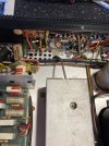
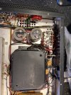
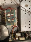
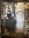
Here are the before pics.

It was stock but I do see a melted cap in the tuner possibly from the original build. Tuner works.

I may go with radial caps since I just bought a big stock from b+d enterprise of Sanyo sun con caps from Japan which were rated well.

I like the model 19 a lot too.
 

Attachments

  • IMG_7662.jpeg
    IMG_7662.jpeg
    162.2 KB · Views: 66
  • IMG_7694.jpeg
    IMG_7694.jpeg
    136.2 KB · Views: 64
  • IMG_7691.jpeg
    IMG_7691.jpeg
    124.4 KB · Views: 61
  • IMG_7690.jpeg
    IMG_7690.jpeg
    115.6 KB · Views: 62
  • IMG_7679.jpeg
    IMG_7679.jpeg
    154.3 KB · Views: 62
  • IMG_7671.jpeg
    IMG_7671.jpeg
    145.5 KB · Views: 59
  • IMG_7668.jpeg
    IMG_7668.jpeg
    136.1 KB · Views: 56
  • IMG_7665.jpeg
    IMG_7665.jpeg
    142.9 KB · Views: 56
  • IMG_7663.jpeg
    IMG_7663.jpeg
    147.4 KB · Views: 60
Register to hide this ad
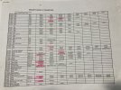
I forgot I used this list for my model 19 and it didn’t explode so I’ll reference it where needed. I decided to change the nearby resistors that I see that have paint flaking off near the caps I’m replacing (are these the deposited carbon ones?) I’ll probably keep the diodes if they test good. Each time at the bench a little further. Picked out some nice e-caps substituting 390/65 for the 350/50 near the driver boards.
 

Attachments

  • IMG_7755.jpeg
    IMG_7755.jpeg
    162.3 KB · Views: 24
I did a thing!
I think this is a world record for me recapping. I used some primitive methods since I was able to use all parts I had in stock but for me the point is the performance. It is working great and the scope is bright. I didn’t have to take anything but the top and bottom cover off either. I may leave the preamp stock for a bit.
 

Attachments

  • IMG_7783.jpeg
    IMG_7783.jpeg
    107.6 KB · Views: 63
  • IMG_7784.jpeg
    IMG_7784.jpeg
    147.8 KB · Views: 64
  • IMG_7785.jpeg
    IMG_7785.jpeg
    134.4 KB · Views: 68
  • IMG_7786.jpeg
    IMG_7786.jpeg
    133.1 KB · Views: 64
It looks good though. You didn't just leave them loose hanging by the leads.
Once you get the preamp section done it should really shine. I think the model 18 was one of, or the last piece of equipment Saul Marantz was involved with from the beginning to the end of the design.
 
It looks good though. You didn't just leave them loose hanging by the leads.
Once you get the preamp section done it should really shine. I think the model 18 was one of, or the last piece of equipment Saul Marantz was involved with from the beginning to the end of the design.

The 18 sure sounds good. I was thinking on my pioneer hpm 40s…man the previous marantz 2250 did shine. It didn’t open up until I hooked it up to fm radio last night on my Tannoy 10” hpd in custom cabinets. Then I could tell the midrange detail that it can reproduce. The lows and highs are very fun sounding. I love it.
 
Ita good to hear the FM sounds good. Tuners and tuner sections are something I don't like to mess with.
 
Ita good to hear the FM sounds good. Tuners and tuner sections are something I don't like to mess with.

Never have yet myself. Thinking of learning eventually. It took me a while just to learn how to repair without replacing every single part.
 
Update I took the tuner section apart to clean. My dumb luck caused the string to completely slip off. First time I’ve had to restring a tuner. I hope I didn’t knock the alignment off but the one side stayed attached so it should be close enough in my initial testing. But it was really dirty under that cover and I could tell it wasn’t as sensitive as the 20 I just cleaned. This ought to do the trick.

Now every single electrolytic has been replaced.

I also installed a grounded AC cord.


Dc offset and bias set. One channel had dc offset 20 mv the other 35. I had to clean the pots. One bias was set to 150 mv instead of 80. The other was 85. Now they are all back to spec.

Unfortunately my phono has a channel out. Well the phono bias reads nearly 0 on the one channel instead of the 20 v spec. I was hoping the transistors were in sockets to pull them but they are solid in there. I now am going to print a schematic and start checking voltages. The worst part is trying to remove this board due to the phono cables to and from the preamp sections…there is no slack or room to resolder. The other channel read about 23v instead of 20.
 

Attachments

  • IMG_7849.jpeg
    IMG_7849.jpeg
    156.5 KB · Views: 27
  • IMG_7848.jpeg
    IMG_7848.jpeg
    116.7 KB · Views: 28
I was able to swing the phono board out hopefully enough to desolder components. Those are not transistor sockets but some kind of spacer / insulator. ugh a wire broke. Looks like I will have to fix that too.
 

Attachments

  • image.jpg
    image.jpg
    128.5 KB · Views: 27
Here’s where the fun begins. I will start checking the resistors on the bad channel since it’s important if a shorted transistor can affect the resistor or vice versa. Will check the diodes. Then I will pull the transistors if I don’t find anything.
 

Attachments

  • IMG_7920.jpeg
    IMG_7920.jpeg
    153.3 KB · Views: 8
Back
Top Bottom